Open this page in a new tab

Gulf of Aqaba

Gulf of Aqaba in Google Earth

click on image to explore this site on a new tab in Google Earth


Aerial Views, Maps, and Cores
Tectonic and Bathymetric Maps

Aerial Views

  • Gulf of Aqaba in Google Earth

Tectonic setting of entire Gulf of Aqaba

Figure 1

(A) Tectonic setting of the sinistral strike-slip Dead Sea Fault (DSF). Seismicity from the ISC earthquake catalogue 1964 - 2015 (http://www.isc.ac.uk). The DSF connects to the North to the East Anatolian Fault System (EAFS) and to the South to the Red Sea ridge (modified from Le Béon et al., (2008)) GA: Gulf of Aqaba, ST: Strait of Tiran.

(B) Multibeam bathymetric map of GA and ST with the main active faults, combining R/V Thuwal (2018), F/S Meteor (1999) and Hall & Ben Avraham (1978) datasets. The main strike-slip faults are in red while normal faults are in black. Fault traces have been simplified for clarity. The grey focal mechanisms corresponding to the successive sub-events for the, Mw 7.3, 1995 earthquake, and location of the seismic swarms in 1983, 1990, 1993 and other focal mechanisms after Klinger et al., (1999). Grey background is Landsat 8 Imagery, courtesy of the U.S. Geological Survey (2018).
  • ArF: Arnona Fault
  • AF: Aragonese Fault
  • DF: Dakar Fault
  • EF: Eilat Fault
  • HF: Haql Fault
  • TF: Tiran Fault
Matthieu et al. (2021)

Bathymetric Maps

Figure 2
  1. Bathymetric map of the Gulf of Aqaba combining R/V Thuwal (2018), F/S Meteor (1999) and Hall & Ben Avraham (1978) datasets
  2. Shade bathymetry of the Gulf of Aqaba with an azimuth of 315N and a sun angle of 25°
  3. Slope map of the Gulf of Aqaba from low slope angle (white: 0°) to high slope angle (black: >45°)
All maps are projected in WGS 84 - UTM 36N. On-land grey background from a Landsat-8 image, courtesy of the U.S. Geological Survey.

Matthieu et al. (2021)

Fault Map - North Gulf of Aqaba

Figure 3
  1. Zoom-in of the northern part of the Gulf of Aqaba, along the morphological trace of the Haql fault (see location on Figure 2) with location of the cross sections shown in (B). The fault lines are more detailed than in Figure 1. Red lines represent the main strike-slip faults, black lines the main normal faults. Along the Eilat fault, a long-term displaced channel as well as the left-lateral displacement of a small hill confirm the strike-slip character of the Eilat fault.
  2. Cross-sections along the longitudinal shape of the alluvial fans, North of the city of Haql. No vertical offsets are visible on these cross-sections, with the exception of a possible knickpoint along profile D-D’. The continuous convex shape of the fans suggests no recent activity of the Haql fault.
  3. The trace of the Haql fault is buried by fans coming from the coastal plain, with no visible recent perturbations of the fans at this location. Nevertheless, the high relief shows the long-term normal or oblique character of the Haql fault. In few places, the shaded topography suggests that a small part of strike-slip motion is also accommodated along the Haql fault.
  4. At the southern termination of the Haql fault, discontinuous small scarps across the fans suggest that this section of the fault might have been activated recently.
Matthieu et al. (2021)

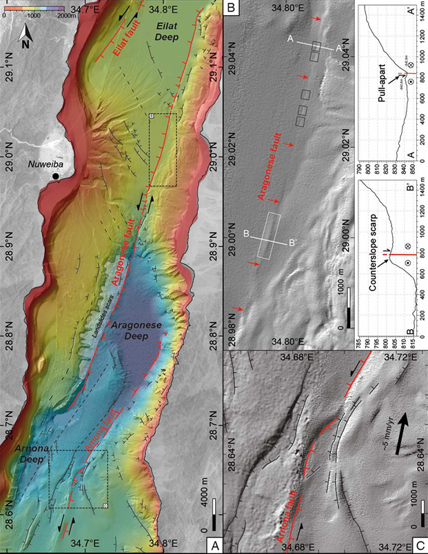
Fault Map - Central Gulf of Aqaba

Figure 4
  1. Detailed fault map of the sinistral strike-slip fault system in the central GA. Direct evidence of surface rupture associated to the main subevent (see Fig. 2) of the 1995 Mw = 7.3 Nuweiba earthquake are found in box B.
  2. Sharp fault morphology suggesting very recent fault activation. Small changes of geometry along the Aragonese fault are responsible for small pull-apart (black squares) and counterslope scarp (white square).
  3. Detail of the fault zone between Aragonese Deep and Arnona Deep resulting from a complexity in the geometry of the Arnona fault. The red line represents the main active strike slip fault.
Matthieu et al. (2021)

Fault Map - South Gulf of Aqaba

Figure 5
  1. Southern part of the Gulf of Aqaba (see location on Figure 2). Dakar and Tiran Deeps are located between the sinistral strike-slip Arnona fault (red line) and the normal Dakar fault (bold black lines). The location of the main strike-slip fault is partly masked by diapiric foldings (black arrows) and secondary faulting (thin black and dashed black lines) associated with the destabilization of large salt deposits moving down from the Dahab plateau.
  2. Cross-sections across the Dahab plateau showing the eastward sloping and the topographic drop from the Dahab plateau toward the Dakar and Tiran deeps.
Matthieu et al. (2021)

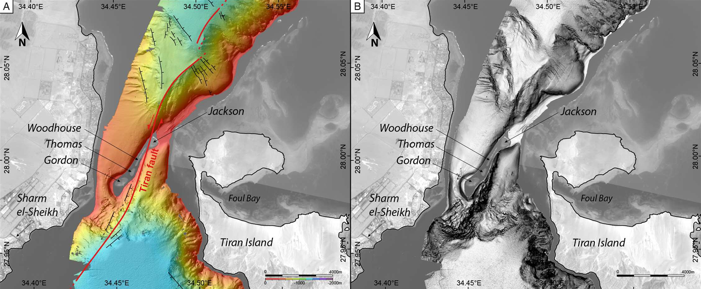
Fault Map - Strait of Tiran

Figure 6

Strait of Tiran (see location on Figure 2).
  1. The sinistral strike-slip Tiran Fault is located between the Woodhouse and Jackson reefs. The sharp bathymetry to the North and to the South of the reef emphasizes the location of the fault. Red lines represent the main strike slip faults, black lines represent the main normal faults.
  2. Slope map of the Strait of Tiran, from low slope angle (white: 0°) to high slope angle (black: >45°).
Matthieu et al. (2021)

R/V Mediterranean Explorer Cores (N Gulf of Aqaba)

Aerial Views

  • Gulf of Aqaba in Google Earth

Location Map

Elat Cores Fig. 1

(a) Regional tectonic map of the Dead Sea Transform and location of the Gulf of Aqaba/Elat

(b) Topographic image map of the southern Arava Valley showing location of the study area of the Elat Sabkha. Previously mapped faults in black lines (after Garfunkel, 1970; Garfunkel et al., 1981; Sneh et al., 1998). Previous study sites including Avrona Sabkha and Yovata Sabkha and locations of the paleoseismic trenches (in block circles)
  • QT = Qatar trench (Klinger et al., 2015)
  • AT = Avrona Trenches (Amit et al., 1999; Zilberman et al., 2005)
  • ST = Shehoret trenches (e.g. Amit et al., 2002)
  • GAE = Gulf of Aqaba/Elat

CMP shots discussed in this study from seismic lines SI-4047 and GI-2108 are plotted as light-blue dots and yellow dots, respectively. The blue rectangle marks the extent of the study area maps presented in Figs. 3 and 9. The pink line represents the location of the offshore high-resolution seismic profile by Hartman et al. (2014) detailed in Fig. 2b.

Kanari et al (2020)

Core Location Coordinates

Core Latitude Longitude Water Depth (m)
P12 29.505689 34.980594 460
P17 29.504708 34.969085 540
P22 29.504716 34.936025 320
P27 29.506122 34.952225
P29 29.487288 34.918868 280

Cores and other data

Article Excerpts

Ash-Mor et al. (2017)

Abstract

Submarine mass transport deposits (MTDs) are a well-known phenomenon in tectonically active regions. Evidence for such deposits is commonly found in the continental slope sedimentary records, as distinct units with coarser grain size compared to the usual and continuous pelagic sedimentation. The Gulf of Eilat/Aqaba is located between the southernmost end of the Dead Sea transform and the spreading center of the Red Sea, and is considered as an active tectonic region.

In this study, an innovative approach using symbiont-bearing Larger Benthic Foraminifera (LBF) to identify MTDs in the Gulf of Eilat/Aqaba (GEA) sedimentary record is presented. The abundance, size and preservation state of LBF shells were analyzed in two radiocarbon dated sediment cores collected at different deposition environments, at water depth of 532 m and 316 m.

The microfaunal and taphonomic results show that the coarse units are characterized by a generally higher numerical abundance of LBF, dominated by Operculina ammonoides, Amphistegina papillosa and Amphistegina bicirculata. These benthic assemblages are found in deeper depths than their original habitat, ranging between 50 and 120 m, in accordance with their symbionts light requirements. In the coarse units, LBF> 1 mm appear in high frequency, up to 161 specimens per g sediment, and poorly preserved shells are also abundant, containing up to 247 specimens per g sediment. In addition, these units also contain high numbers of yellowish and blackish colored LBF shells, as opposed to null in the non-disturbed units, and unlike their natural white color.

The large shell size indicates that high energy is involved in the displacement of the sediments. The poor state of preservation also suggests a turbulent flow during transportation, which requires a high-energy triggering mechanism. The color alteration is probably associated with a diagenetic process related to increasing burial time/depth, also supported by the stratigraphic older ages of the MTDs, suggesting a long burial before the sediments were displaced. In addition, according to the dating of the record, some units correlate with historical and pre-historical earthquakes, reinforcing LBF species as a reliable proxy for mass transport events.

Introduction

Submarine mass transport deposits (MTDs) are recognized as im portant sedimentary facies in the marine environment. These deposits exhibit distinct characteristics (Ducassou et al., 2013; Gao and Collins, 1994; Masson et al., 2006) and are used to infer transport processes in different geodynamic settings. The displacement process is known to be associated with sea level fluctuations, ice rifting, river mouths, high sedimentation rates, tropical storms, tsunami backwash, and particularly in tectonically active continental margins (Griggs, 2011; Hampton et al., 1996; Maslin et al., 2005; Polonia et al., 2015; Sugawara et al., 2009; Wright and Anderson, 1982; Yordanova and Hohenegger, 2002; Zabel and Schulz, 2001).

Mass transport deposits consist of recycled sediments initially deposited at the continental shelf and gravitationally transported down the continental slope to deeper water depths. The transport and deposition are strongly grain size selective, resulting in a distinctive texture of coarser sediments, often finning upwards, distinguishable from the finer pelagic continuous deposition (Ducassou et al., 2013; Gao and Collins, 1994; Masson et al., 2006). In some cases, increased organic carbon concentrations point to rapid burial and high preservation that also serve as indicators for MTDs (de Haas et al., 2002; Ducassou et al. 2013;Zabel and Schluz, 2001)

Benthic foraminifera species, which are generally restricted to a specific depth range due to their ecological adaptations, can also serve as indicators for MTDs. In undisturbed conditions, their assemblages vary depending on increasing water depth, substrate type, oxygen content and organic matter flux (Edelman-Furstenberg et al., 2001; de Stigter et al., 1998; Hohenegger, 2004; Jorissen et al., 1995; Murray, 2006). However, instantaneous mass movement events can transport benthic foraminifera along with the sediments and re-deposit them downslope, in a deeper environment compared to their natural habitat. Considering the depth ranges and the ecological requirements of the transported species, it is possible to infer the original deposition depth of the displaced sediments (e.g. Ducassou et al., 2013). Large symbiont-bearing benthic foraminifera (LBF), which are re stricted to the photic zone, are particularly good indicators for MTDs as their depth range is more limited than that of deep sea species (Hallock and Hansen, 1979; Hohenegger et al., 1999; Reiss and Hottinger, 1984). Therefore, sediments derived from a shallow water depth may be easier to recognize and their original depth of deposition can be determined accurately.

The state of shell preservation (taphonomy) can also be used to characterize mass transport processes. In a laboratory experiment, Beavington-Penney (2004) examined the effect of transport distances on shell breakage. Distinguishing between different preservation states of Palaeonummulites venosus, lead them to conclude that the most poorly preserved shells were transported under turbidity current conditions.

Shell coloration is also a taphonomic parameter that can be used to detect sediment mixing in transportation and resuspension processes. Yordanova and Hohenegger (2002) studied black and/or brown LBF shells at water depths of up to 100 m off the shore of western Okinawa, Japan, and suggested that the blackish color is the result of pyritisation and iron sulfides precipitation under anoxic conditions due to sediment burial. Furthermore, the yellowish-brown color is the outcome of limonitisation, a re-oxidation of the pyrite into ferric oxide, due to sediment mixing caused by tropical storms typical to the area.

Here, we focus on fossilized LBF assemblages as a biomarker for the identification and characterization of MTDs in the seismically active region of the northern Gulf of Eilat/Aqaba (GEA). The foraminiferal analysis of sediments in piston cores collected from the gulf enables to establish LBF as a reliable proxy for mass transport events.

Western slope core- MG10P22

The bulk of the sediments in this core is generally fine grained with less than 20% coarse size fraction greater than 63 μm. The core record is dissected by two distinct coarser sediment layers of MTDs occurring between 50–56 cm (P22A) and 170–180cm (P22E). These layers comprise of 75–90% coarse fraction. The sediment in these layers is composed of large biogenic (e.g. molluscs, corals, echinoids as well as LBF) and rock fragments. In addition, three layers of slightly coarser sediments are also identified at 65–68 cm (P22B), 79–82 cm (P22C) and 120–134 cm (P22D), containing 18–27% coarse fraction> 63 μm (Figs. 5, 6).

Core MG10P22 spans approximately the last 13 ka (Table 1; Fig. 5). Radiocarbon ages above the MTDs represent the chronological age of these events: unit P22A is dated to 4071 ± 55 cal years BP and unit P22E dates to 7416 ± 42. The former reveals no unconformity caused by the displacement event, while the latter reveals a ~ 5000-year hiatus (Table 1, Fig. 6). The sediments within these units are dated by the age of the displaced LBF: unit P22A is dated to 9364 ± 58 and 10,087 ± 79 cal years BP, and unit P22E to 11,074 ± 87 and 11,759 ± 142 cal years BP, with whitish shells slightly younger than the yellowish shells (Table 1; Fig. 5).

The most common LBF in the core material are Operculina ammonoides and several species of Amphistegina, mostly A. papillosa and A. bicirculata, and also A. aff. A. radiata and A. lessonii that occur in low numbers. The depth ranges of A. aff. A. radiata were similar to that of A. papillosa (Hottinger et al., 1993), and in some cases they were difficult to distinguish (especially juveniles and poorly preserved shells). Therefore, these two species were combined into a single group of A. papillosa & A. radiata. The abundance of the most common LBF species in the displaced sediment layers is much higher than in the pelagic sediments. Furthermore, the dominant species in this core are A. bicirculata and A. papillosa + A. radiata followed by O. ammonoides (Fig. 7).

The LBF occurred in the coarser units in higher numbers, with many shells greater than 1 mm, and with more poorly preserved shells frequently having a yellowish/blackish color. In contrast, the specimens in the fine pelagic sediments, if present, are mostly juvenile, and larger and colored shells are scarce (Fig. 7).

In the coarser units P22A and P22E, the total number of LBF shells larger than 1 mm amounts to 18.8 specimens per g sediment. In contrast, the pelagic sediments amount to 6.6 specimens per g sediment, as most of the specimens in these sections, if present, are smaller than 1 mm.

The number of broken shells (greater than 50%) of Amphistegina spp. in the coarse sediments amounts to 28.3 specimens per g sediment, as opposed to 3.7 specimens per g in the pelagic sediments. In addition, the number of broken shells (greater than 50%) of the less abundant O. ammonoides in the coarse sediments amounts to 3.3 specimens per g sediment, as opposed to 1.1 specimens per g in the pelagic sediments.

Total yellowish shells in the coarse units amounts to 18.1 specimens per g sediment, as opposed to 2.8 specimens per g in the pelagic sediments. Blackish shells are extremely rare in this core (Fig.7).

Submarine canyon core – MG10P27

MG10P27 spans a shorter time period compared to MG10P22, only the last 2300 years (Table 1, Fig. 5). The sediments in this core are generally fine grained as well, with less than 20% of the coarser greater than 63 µm size fraction. These sediments are intersected by five distinct units of coarse sediments occurring between 0 and 10 cm (P27A), 18 and 25 cm (P27B), 38 and 45 cm (P27C), 105 and 110 cm (P27E) and 112 and 145 cm (P27F) at the bottom of the core, with material > 63 µm comprising 70-98% of the entire sediment (Fig. 6). In addition, one more unit of slightly coarser sediments occur at 80-82 cm (P27D) containing 29% fraction > 63 µm. The composition of these units is similar to the material mentioned above in MG10P22.

Due to suspected mixing of the core top, the upper 25 cm were not dated or analyzed for LBF. The sediments below unit P27B were dated to 658 ± 34 cal years BP, while units P27C, P27D and P27E were dated to 1067 ± 42, 2093 ± 56 and 2261 ± 57 cal years BP, respectively. The sediments within these layers were dated between 3482 ± 41 and 5440 ± 49 and contained only whitish and blackish shells. No dating analysis was conducted between units P27E and P27F due to the lack of material for dating. Sediments within unit P27F were dated in a 10-cm resolution varying between 4409 ± 52 and 6523 ± 46, with white shells being the youngest and blackish shells the oldest. Yellowish shells occur only in this unit (Table 1, Fig. 5).

The same species that occur in MG10P22 also appear in MG10P27, although in this core O. ammonoides is the dominant species, followed by A. papillosa (Fig. 7). The overall abundance of these species in core MG10P27 is an order of magnitude higher than in MG10P22. A. bi-circulata is rare in this core. Other LBF species such as Sorites orbiculus, Peneroplis planatus and Heterostegina depressa also occur in both cores though in much lower numbers (Fig. 7).

In the MTDs of MG10P27, LBF larger than 1 mm consist of up to 161.2 specimens per g sediment. In contrast, the pelagic sediments in this core consist of up to 3 specimens per g. The no. of broken shells ( > 50%) of Amphistegina spp. in the coarse sediments amounts to 86.8 specimens per g sediment, as oppose to 7.1 specimens per g in the pelagic sediments. The number of broken shells ( > 50%) of the highly abundant O. ammonoides in the coarse sediments amounts to 190.5 specimens per g sediment, as oppose to 19 specimens per g in the pelagic sediments.

The total number of blackish shells in the coarse units amounts to 132 specimens per g sediment, as opposed to 13 specimens per g in the fine pelagic sediments. The total number of yellowish shells in the coarse units amounts to 12.4 specimens per g sediment, as opposed to 0.1 specimens per g in the fine pelagic sediments (Fig. 7).

Ages from within the mass transport deposits

The ages from within the MTDs are significantly older than the pelagic sediments above and below them, due to their recycling from a prior deposition site. Anomalous older age, unfitting the core stratigraphy, can serve to identify the occurrence of displaced sediments.

The difference between the age of the MTDs and the chronological age of the displacement event, dated above the MTDs, places the burial time of the sediments at the continental shelf before the mass transport event. In the two studied cores, the maximum age differences range from 2681 years (unit P27C) to 6016 years (unit P22A;Fig. 5), suggesting that the sediments were buried for ~2500 to ~6000 years on the continental shelf prior to their displacement.

In some cases, as occurs in unit P22E of the slope core, the age from within the MTD appears not to be anomalously old, and the sedimentary sequence may seem continuous (Fig. 5). However, the chronological age of this unit, dated to 7416 ± 42 ka BP, indicates ~4600 years of sediment removal by this event and an unconformity in the record (Figs. 5,6).

In the canyon core, all three intervals dated in unit P27F reveal similar dating results (Fig. 5), suggesting that this layer originated from the same sediment pack in one massive event. The shorter residence time of sediments on the northern shelf, feeding the canyon core record, together with the higher frequency of MTDs, points to a larger volume of sediments available for transport relative to the western slope.

Sediments availability and sedimentation rates

... Repetitive mass transport events may appear as a single event in the sedimentary record (Martín-Merino et al., 2014), which could serve as a possible explanation for the thick P27F unit in the canyon core. Nevertheless, this unit seems to be the result of a single massive event, as it presents a typical graded bedding accumulation pattern known to occur in turbidites (Mulder and Alexander, 2001). The LBF abundance supports this suggestion. As the sediments grow coarser towards the bottom, the numerical abundance of foraminifera gradually decreases(Figs. 5 and 7). Although the bottom of unit P27F was not recovered,these opposite trends of grain size and LBF occurrence, combined with the similar dating results from within this unit, strengthened the interpretation of a single massive event. In contrast, in the western shelf [e.g. slope core P22], where less sediments accumulate, a single high magnitude event may displace a large amount of sediments, and therefore reduce or even eliminate the volume of sediments available for transport in the following event, suggesting that the record is incomplete.

The differences in the sedimentary record of the two deposition environments show that, regardless of the small distance between them,the recorded events depend strongly on the accumulation rates and the sediment source site. While the pelagic material accumulates relatively equally throughout the water body, the MTDs in the canyon core comprise ~50% of the total sedimentary record, compared to ~11% in the slope core. This highlights the contribution of MTDs to the sedimentary record, and the importance of mass transport processes in the GEA. Moreover, it emphasizes the crucial understanding of the different surroundings and bathymetric settings where a study is conducted.

Travel distance and source area estimation

Based on the composition of the LBF assemblages, the displaced sediments in both regions originate from a water depth of approximately 50-120 m (Perelis-Grossowicz et al., 2008; Reiss and Hottinger, 1984; Fig. 1). However, the foraminiferal results show distinct differences between the two cores, reflecting the different expression of the same process in different environments. The abundance of LBF species per g dry sediment in the canyon core is ten times higher than in the slope core (Fig. 7). A suggested explanation is that the submarine canyon is transporting sediments that originate from a wider source area.

Based on GIS "watershed" analysis, the estimated source areas are 7.8 km2 and 0.47 km2 for the canyon and the slope core, respectively. Considering the 50-120 m depth range of the MTDs assemblage's habitat (Hottinger, 2008; Perelis-Grossowicz et al., 2008; Reiss and Hottinger, 1984), the sediment source areas are 3.5 km2 and 0.25 km2, respectively (Fig. 8), reinforcing this suggested explanation. The travel distance of sediments from the shelf edge at 120 m, is ~3.7 km to the location of the canyon core, and ~0.75 km. to the slope core. These distances are not as long as those known for turbidites in open ocean (Griggs, 2011; Hampton et al., 1996; Khripounoff et al., 2003; Locat and Lee, 2002; Mulder and Alexander, 2001; Tailing et al., 2007), yet four MTDs occur in the past 2500 years in the canyon core, while no such units appear in the slope core in this time period. The different MTDs occurrence in the two records is apparently related to the amount of available portable sediments, which is connected not only to the source area, but also to the bathymetric features of the continental shelf, providing the sediments accumulation space.

Shell size and mobilization

The coarse MTDs are characterized by LBF with a generally larger shell size (Fig. 7), with A. papillosa reaching a maximum diameter of 1.5 mm, A. bicirculata of 2 mm and O. ammonoides of ~4 mm. In contrast, the pelagic sediments contained only a few juvenile specimens, with a shell diameter of 150-250 µm, if any. The larger shell size represents adult specimens living and dying in their natural habitat prior to the abrupt event that triggered the displacement. Larger grains and shells require higher energy and current velocities in order to be moved as particles.

Yordanova and Hohenegger (2007) examined threshold friction and entrainment velocities and showed that A. bicirculata and A. papillosa with a shell diameter of 1.5 mm and O. ammonoides with a shell diameter of 3 mm, require velocities of ~18 cm/s for entrainment on a flat rough surface. The rare occurrence of LBF > 150 µm in the fine pelagic sediments suggests that sediments of this size are not transported from the shelf area to the deep sea-bed under natural conditions. Therefore, the larger shell size of the LBF in the MTDs is another indicator for transport from the outer continental shelf to a deeper depth by high velocity events.

Taphonomy

Degree of breakage

The coarse MTDs are also characterized by high abundance of broken LBF shells (Fig. 7). This indicates turbulent conditions during transport causing a high degree of shell abrasion and fragmentation, unlike the excellent preservation of planktonic and deep water benthic foraminifera found in the fine pelagic sediments. Beavington-Penney (2004) simulated the transport of Palaeonummulites venosus shells under laboratory conditions, and analyzed their fragmentation and abrasion features. According to this study, > 50% of shell fragmentation is related to transport distance > 70 km, predation by large bioeroders or transport within turbidity currents. Considering the relatively short distance of transport in the current study area (Figs. 2 and 8), it is believed that the turbulent flow associated with mass transport processes is the cause of the highly fragmented shells found in the MTDs.

Turbulent flow requires a high-energy triggering mechanism and steep bathymetry. The high abundance of > 1 mm and broken LBF shells in the MTDs, combined with the steep bathymetry of the GEA slope (Tibor et al., 2010), requires much higher current velocities than the velocities measured in the gulf (Biton and Gildor, 2011; Khripounoff et al., 2003; Wynn et al., 2000). Therefore, the GEA's regional tectonic activity is a potential trigger for these mass transport events.

Shell coloration

The displaced sediments in the MTDs are characterized by a relative abundance of colored LBF shells, corresponding to their larger shell size and poor preservation (Fig. 7). In the slope core, colored LBF shells found within the MTDs occurred with yellowish color, whereas in the canyon core shells appeared with both yellowish and blackish color (Fig. 7). The coloration of biogenic particles in the GEA has not been studied yet, although black shells of O. ammonoides were found to be present in surface sediments from the northern shelf (Perelis-Grossowicz et al., 2008).

LBF shell coloration is assumed to be associated with postmortem processes and burial depth (Maiklem, 1967; Yordanova and Hohenegger, 2002). The latter described a linear diagenetic process affecting foraminifera shells, starting with pyritisation due to anoxic conditions caused by sediment accumulation and burial, followed by limonitisation associated with re-ventilated conditions due to tropical storms. This led to the suggestion that colored shells may also serve as an indicator for identifying MTDs that consist of older recycled sediments.

In this study, the re-oxidation may be the outcome of the turbulent flow during the mass transport events. Sediments, which were long buried, were mixed and exposed once again to the oxygenic water column before their redeposition in the final deeper terminal accumulation area. Since the coloration is a diagenetic process developed over time, we expected an age difference with colored shells being older than the pristine white shells.

The dating results of LBF taken from the MTDs in the canyon core support the process described above, as the blackish and yellowish shells were found to be older than the white shells at a range of a few hundred up to 2060 and 1222 years, respectively. Yellowish shells were found only in unit P27F, yet their age was consistently younger than the blackish shells by 300 to 1400 years (Table 1. Fig. 5). In the slope core, no black shells occur, and the yellowish shells suggest that all pyrite containing shells are apparently oxidized to limonite upon their transport. However, the dating results of the yellowish shells from both units pre-date the pristine white shells by 700 years, suggesting a more complex process of diagenesis related to post-mortem secondary calcite precipitation. Moreover, the higher abundance of yellowish shells in unit P22A, rather than unit P22E (Fig. 7), suggests that only a part of the sediments from the source area were transported during the deposition of unit P22E. Therefore, the sediments of unit P22A were buried for a longer period on the continental shelf, enabling the diagenetic process to progress before being transported.

Foraminiferal proxies, both shell size and taphonomy, for MTDs also appear in units that cannot be distinguished based on grain size alone, as in units P22B - P22D of the slope core and unit P27D of the canyon core (Fig. 7). This reinforces the reliability of foraminifers as a proxy for the identification of small scale mass transport events, as well as large scale events.

Earthquakes as triggers for mass transport events

Mass transport events are known to be associated with tectonic activity (Griggs, 2011; Locat and Lee, 2002; Polonia et al., 2015). The northern GEA is a tectonically active zone (Ben-Avraham, 1985; Ehrhardt et al., 2005; Klinger et al., 1999; Shaked et al., 2011), and seismic activity is a possible trigger for mass transport events.

The chronology of MG10P27 covers the historical period, which is well documented in seismic catalogues and geological records (Ambraseys et al., 1994; Amit et al., 2002; Kagan et al., 2011; Ken-tor et al., 2001; Khair et al., 2000). According to Kanari (2016), unit P27C in the canyon core coincides, within the error range, with a ~7MW earthquake which occurred in 948 years BP (1068 CE) and caused heavy destruction to Aqaba (Ambraseys et al., 1994; Ben-Menahem, 1991; Kagan et al., 2011). In addition, a major surface rupture of > 12 km in length documented north of Eilat, caused by a seismic event of at least 7MW and dated between 900 and 1000 years BP (Zilberman et al., 2005), correlates to this event.

The chronological sequence of MG10P22 reveals a pre-historical period too old for documentation in seismic catalogues. Nevertheless, the two MTDs in this core, P22A and P22E, correlate well with two catastrophic events described by submerged fossilized coral reefs (Shaked et al., 2004, 2011). Unit P22A correlates well with an earthquake event suggested by Shaked et al. (2004, 2011) to have occurred ~4.7 ka BP. Unit P22E, dated to 7416 ± 66, correlates well with the initial growth of fossilized corals, dated to at least 7 ka BP, suggesting that this unit served as the substrate for the corals settlement. The occurrence of these two events documented in the coastal area of the gulf, in association with the slope core from the deep sea, reinforces the assumption of a physical barrier, as suggested above, preventing shallow water sediment and benthic fauna from being transported to the deep sea during these events. Evidence for the intensity and widespread influence of these two events was also identified at the northern extension of the Dead Sea Transform, in sedimentary cores from the shores of the Dead Sea (Kagan et al., 2011).

The correlation of the MTDs found in the studied cores with known and previously studied seismic events strengthens the hypothesis of seismic activity as the triggering mechanism in this study area. Furthermore, if the taphonomy of the LBF (% of poorly preserved shells), which is dictated by the mass transport intensity, is used as a proxy for the local intensity of the triggering event, it is possible to distinguish between small, intermediate and large-scale events vs. the pelagic sediments (Fig. 9). However, it should be noticed that the number of specimens is highly dependent on the depositional settings, and the MTDs of the western slope vs. the submarine canyon need to be distinguished.

Conclusions

The Gulf of Eilat/Aqaba (GEA) continental slope cores display coarse sediment units with distinct micropaleontological and taphonomic features, indicative of displaced sediments. These units are characterized by a sharp increase in the abundance of symbiont-bearing Larger Benthic Foraminifera (LBF) with large shell size and poor preservation, suggesting an abrupt and energetic triggering event and turbulent transport. Shell coloration appears to be associated with the large shell size and poor preservation, and probably indicates a long burial before the displacement and re-oxidation during an instantaneous transport event. Nevertheless, further geochemical analysis is required in order to understand the diagenetic processes involved.

Larger symbiont-bearing benthic foraminifera were found to be a useful tool to identify mass transport deposits (MTDs). According to the LBF assemblage found in the MTDs at the GEA, these deposits originate from the deeper shelf area, at a water depth of 50-120 m. The dating results of the displaced LBF are anomalously older than the pelagic sediments above them, suggesting that sediments accumulated at the deep shelf, a few thousand years before the transport.

Although both cores present similar LBF characteristics, their different deposition environment also dictates differences in the MTDs record. The canyon core, fed by a wider and moderate shelf area, presents a higher frequency of events and a larger volume of transported sediments, with a chronologically younger age of the accumulating MTDs. The slope core shows a lower frequency of events transporting a smaller sediment volume. In addition, considering that mass transport events are not necessarily expressed by anomalous ages, as seen in unit P22E, it is concluded that in the study of MTDs, age anomalies should be used only to support other proxies such as grain size, organic carbon content and displaced benthic fauna.

The correlation between the young MTDs and known earthquakes reinforces the hypothesis that seismic events are the triggering mechanism. We conclude that LBF serve as a useful and reliable proxy for the identification and investigation of mass transport events in general, and those triggered by earthquakes in particular.

Kanari et al. (2015)

Abstract

Located at the Northern tip of the Gulf of Aqaba-Elat, the on-land continuation of the submarine Avrona Fault underlies the Hotels District of Elat, where seismic deformation was documented after the 1995 Nuweiba (Sinai) earthquake (7.2 MW). This active segment of the Dead Sea Fault is the transition between the deep marine basin of the Gulf and the shallow continental basin of the Arava Valley. Paleoseismic trenching revealed the fault, based on surface rupture and liquefaction features. Radiocarbon dating of the offset strata and liquefaction suggest that it ruptured in the historical earthquakes of 1068 and 1458 AD, yielding a vertical slip rate of ~1.1 mm/yr. Independent dating of anomalous coarse grain events in core sediments from offshore nearby suggests these earthquakes triggered marine sediment mass-flow. Using this pattern, we analyze anomalous coarse grain events in several cores to compile a paleoseismic record dating back to the late Pleistocene.

Introduction

At the north tip of The Gulf of Aqaba-Elat (the northeast extension of the Red Sea; Fig. 1), reside the cities of Elat (Israel) and Aqaba (Jordan): major economic, cultural, and recreational centers of southern Israel and Jordan, and vital aerial and naval ports. It so happens that they are both also built on active faults, which have ruptured in the past. Aqaba was completely destroyed in the 1068 AD earthquake (Ambraseys et al., 1994; Avner, 1993), and significant damage to structures in both Elat and Aqaba was inflicted by the Nuweiba (Sinai) earthquake (22.11.1995; MW 7.2) even though the epicenter was located 70 km to the south (Klinger et al., 1999). The estimation of seismic hazard to these neighboring cities is therefore vital. The peaceful hotels and beaches of Aqaba and Elat are located on a tectonic plate boundary, which is also a transition zone between two crustal realms of the Dead Sea Fault system (DSF): the deep en echelon submarine basins of the Red Sea (Ben-Avraham, 1985) and the shallow continental basins of the Arava (Frieslander, 2000), localizing into a single fault strand heading northward.

Previous studies of the submarine structure of the Northern Gulf of Aqaba-Elat (NGAE) suggest slip on the east and west boundary faults is predominantly normal and recently active (Ben-Avraham, 1985; Ben-Avraham et al., 1979; Ben-Avraham and Tibor, 1993). However, recent high-resolution seismic and bathymetric data (Tibor et al., 2010; Hartman, 2012; Hartman, 2015) revealed a complex fault system across the shelf of the NGAE with varying degrees of recent seismic activity. Hartman et al. (2015) conclude that during the Holocene, the submarine Avrona Fault (Evrona Fault in some papers) accommodates most of the strike-slip faulting in this transform plate boundary, between the Sinai sub-plate and the Arabian plate, with an average sinistral slip-rate of 0.7±0.3 mm/yr through the Late Pleistocene and 2.3 3.5 mm/yr during the Holocene. (Fig. 2), and a Holocene vertical slip rate of 1.0 ±0.2 mm/yr, suggesting that its seismic activity has increased through recent time.

On-shore, several works estimated the location of the Avrona Fault at the border of the Elat Sabkha (Garfunkel et al., 1981) and in the vicinity of the Elat hotel district (Wachs and Zilberman, 1994). Using seismic imaging, Rotstein et al. (1994) suggested a vertical deformation band of several hundred meters wide below the eastern part of the Elat Hotel District. Further seismic data was used by Frieslander (2000) to suggest a distinct sub vertical discontinuity in the sediments in the same area in Elat. Active surface faulting was observed following the Nuweiba (Sinai) earthquake in 1995 (epicenter 70 km south to Elat), when an offset street was reported in the same hotels area (Wust, 1997). Some 15 km farther north, Paleoseismic trenching in the Avrona Playa revealed late Pleistocene earthquake ruptures displaced 1-1.5m with estimated magnitudes M6.7-M7, and Holocene earthquakes displacing 0.2-1.3m with estimated magnitudes M5.9-M6.7 (Amit et al., 2002). Zilberman et al. (2005) had extensively detailed the surface rupture of the fault in the Avrona Playa, relating observed surface rupture to the two historical earthquakes affecting the southern Arava valley and the ancient city of Aila: the 1068 AD and the 1212 AD earthquakes. They suggest an earthquake recurrence interval of 1.2±0.3 ka for this fault zone. However, the location and the paleoseismic record of the on-land continuation of the marine Avrona Fault, as it emerges from submarine to terrestrial domain, was not known, and surface rupture from the 1068 AD earthquake south of the Avrona playa was not observed so far. Zilberman et al. (2005) report that there was no way to determine the length of the surface rupture in the Avrona Playa due to obscuring by erosion, younger deposits and incision of alluvial fans.

Results and Discussion

... In an independent analysis of the submarine core P27 (Fig. 4; see Fig. 2 for core location) - several anomalous coarse grain (>2mm, up to several cm maximum) events were observed, while most of the core is of typical pelagic deposition of less than 250 um in grain size. Radiocarbon dating of the anomalous events in the core resulted in a good match between the estimated ages of two anomalous events from the top of the core and the 1068 and 1458 AD earthquakes (Fig. 4). We therefore suggest that the anomalous events in the submarine core P27 correspond to the earthquakes of 1068 AD and 1458 AD, which were also observed independently in T1 and T3 trenches on-land, just several km away to the north.

Following this similar pattern of dating anomalous events in core P27 (validated by historical and on-land observations), several other piston cores were analyzed, and their coarse grain anomalous events ages were determined using radiocarbon dating of foraminifera, gastropod and bivalves: P12, P17, P22 and P29 (460, 540, 320 and 280 mbsl). For some events, more than one anomalous events appear to coincide in time in different cores. We suggest that where anomalous events in different cores coincide in their age constraints – it is most likely evidence for mass flow triggered by earthquake events, driving coarse material from the shallower shelf edge into the deep basin (as opposed to sporadic slumping, or mass flow triggered by flashfloods). These anomalous events, observed in several cores from across the NGAE (Fig. 5), serve as basis for the compilation of an earthquake record dating back to late Pleistocene. We discriminate between events validated in more than one core (high confidence level) and events that appear in one core (low level of confidence). In total, we count seven earthquake events (excluding the 1068 AD and the 1458 AD historically validated core events) of which four are of high confidence level; one event is dated to ca 40ka, but could be of less confidence to to the limitations of the 14C dating method. Zilberman et al. (2005) suggest that 5 earthquakes ruptured the Avrona Playa between 14.2±0.3 and 3.7±0.3 ka, which conform with our marine core sediment dated events, as we identify an event ca 2.5 ka, and event ca 40 ka, and five events in a similar time range.

To conclude, we suggest that by correlating on-land and offshore paleoseismic observations, we have evidence for past earthquakes of the late Pleistocene and Holocene around 2.5, 3-3.3, 4.0-4.2, 5.8-6.3, 7.5, 14-14.5 and possibly an event around 40 ka BP. Some of these events may support evidence for past earthquakes suggested by previous authors.

Canyon Core P27

Grain Size Distribution Logs

Ash-Mor et al. (2017)

Elat Cores Figure 5

3D grain size distribution up to 2 mm (left) and radiocarbon dating results (right) along the canyon core MG10P27. Color bar represent % of grain size differential distribution by volume. Black dots represent the chronological age of the pelagic sediments, whereas diamonds represent the different color groups of LBF shells from within the MTDs.

Ash-Mor et al (2017)

Kanari et al. (2015)

Elat Cores Figure 4

Grain size distribution (downcore spectrum of % volume per grain diameter) and 14C age determinations (cal BC/AD) of core P27 from the northern Gulf of Aqaba Elat. 14C age calibrated using Calib 7.0 (Stuiver and Reimer, 1993) and Marine13 calibration curve (Reimer et al, 2013).

Kanari et al (2015)

Sedimentary Characteristic Log

Elat Cores Figure 6

Sedimentary characteristics of the studied core MG10P27
  1. Core image and scheme describing the MTDs
  2. % sediment > 63 μm
  3. sedimentation rates calculated according to the chronological dating results of the pelagic sediments
Ash-Mor et al (2017)

Foraminifera Log

Elat Cores Figure 7

The distribution of the most common LBF in the canyon core MG10P27
  1. Total count of A. papillosa + A. radiata, A. bicirculata andO. ammonoides
  2. number of LBF smaller and larger than 1 mm
  3. number of pristine, moderately and poorly preserved A. ammonoides
  4. number of pristine, moderately and poorlypreserved A. papillosa + A. radiata
  5. number of white, yellowish and blackish LBF shells
All categories are normalized to 1 g of dry sediment.

Higher values occur in all categories at 18–25 cm (P27B), 38–45 cm (P27C), 82–84 (P27D), 105–110 cm (P27E) and from 112 cm down to the bottom of the canyon core (P27F).

Ash-Mor et al (2017)

Slope Core P22

Grain Size Distribution Log

Ash-Mor et al. (2017)

Elat Cores Figure 5

3D grain size distribution up to 2 mm (left) and radiocarbon dating results (right) along the slope core MG10P22. Color bar represent % of grain size differential distribution by volume. Black dots represent the chronological age of the pelagic sediments, whereas diamonds represent the different color groups of LBF shells from within the MTDs.

Ash-Mor et al (2017)

Kanari et al. (2015)

Elat Cores Figure 5

Grain size distribution (downcore spectrum of % volume per grain diameter) of core P22 (316 mbsl) from the Northern Gulf of Aqaba-Elat; see Fig. 2 for core locations

Kanari et al (2015)

Sedimentary Characteristic Log

Elat Cores Figure 6

Sedimentary characteristics of the studied core MG10P22
  1. Core image and scheme describing the MTDs
  2. % sediment > 63 μm
  3. sedimentation rates calculated according to the chronological dating results of the pelagic sediments
Ash-Mor et al (2017)

Foraminifera Log

Elat Cores Figure 7

The distribution of the most common LBF in the slope core MG10P22
  1. Total count of A. papillosa + A. radiata, A. bicirculata andO. ammonoides
  2. number of LBF smaller and larger than 1 mm
  3. number of pristine, moderately and poorly preserved A. ammonoides
  4. number of pristine, moderately and poorlypreserved A. papillosa + A. radiata
  5. number of white, yellowish and blackish LBF shells
All categories are normalized to 1 g of dry sediment.

Higher values occur in all categories at50–56 cm (P22A), 65–68 cm (P22B), 79–82 cm (P22C), 124–125 cm (P22D) and 170–180 cm (P22E) in the slope core

Ash-Mor et al (2017)

Core P17

Grain Size Distribution Log

Elat Cores Figure 5

Grain size distribution (downcore spectrum of % volume per grain diameter) of P17 (540 mbsl) from the Northern Gulf of Aqaba-Elat; see Fig. 2 for core locations

Kanari et al (2015)

Core P29

Grain Size Distribution Log

Elat Cores Figure 5

Grain size distribution (downcore spectrum of % volume per grain diameter) of P29 (282 mbsl) from the Northern Gulf of Aqaba-Elat; see Fig. 2 for core locations

Kanari et al (2015)

Fence of Grain Size Distribution Logs for P17, P22, and P29

Elat Cores Figure 5

Grain size distribution (downcore spectrum of % volume per grain diameter) of cores P17 (540 mbsl), P22 (316 mbsl) and P29 (282 mbsl) from the Northern Gulf of Aqaba-Elat; see Fig. 2 for core locations

Kanari et al (2015)

Bathymetric distribution of common larger symbiont-bearing foraminifera (LBF)

Elat Cores Figure 1

The bathymetric distribution of common larger symbiont-bearing foraminifera (LBF) from the Gulf of Eilat/Aqaba (GEA). The darker color represents the maximumabundance depth interval. Based on Haunold et al. (1997), Hottinger et al. (1993), Oronet al. (2014), Perelis-Grossowicz et al. (2008) and Reiss and Hottinger (1984).

Ash-Mor et al (2017)

Larger symbiont-bearing foraminifera (LBF) as a proxy for Mass Transport Deposits (MTDs)

Elat Cores Figure 9

LBF as proxy for MTDs in different deposition environments. The % of poorly preserved shells distinguishes between the pelagic sediments and small, intermediate and large-scale events. The number of specimens/g sediment distinguishes between the western slope as opposed to the submarine canyon.

Ash-Mor et al (2017)

Sediment source areas for slope core P22 and canyon core P27

Elat Cores Figure 8

Sediment source areas estimated for the slope core MG10P22 (light blue) and the canyon core MG10P27 (pink) based on GIS “watershed” analysis. The opaque color represents the 50–120 m water depth of the deeper shelf.

Ash-Mor et al (2017)

R/V Thuwal Cores (N, S, and Central Gulf of Aqaba)

Aerial Views

  • Gulf of Aqaba in Google Earth

Fig. 1 - Location Map

Normal Size

Fig. 1

Sediment coring locations in the Gulf of Aqaba.

a) Tectonic setting in the eastern Mediterranean and the northern Red Sea.

b) The bathymetry of the Gulf of Aqaba and active faults (Ribot et al., 2021; Le B´eon et al., 2012) with black dots showing the coring locations. The main strike-slip faults are in red
  • TF: Tiran Fault
  • ArF: Arnona Fault
  • AF: Aragonese Fault
  • EF: Eilat Fault
  • WAF: Wadi Araba
whereas normal faults are in black. Paleoseismic trenching sites are labelled as
  • x (Klinger et al., 2015)
  • y (Amit et al., 1999; Zilberman et al., 2005)
  • z (Amit et al., 2002)
  • t (Kanari et al., 2020)
The top right inset shows the lateral extent of historical earthquakes on the WAF (Klinger et al., 2015).

c-g) Close-up views of the coring locations in the Eilat, Aragonese, Dakar, Tiran and Hume deeps.

Bektaş et al. (2024)

Magnified

Fig. 1

Sediment coring locations in the Gulf of Aqaba.

a) Tectonic setting in the eastern Mediterranean and the northern Red Sea.

b) The bathymetry of the Gulf of Aqaba and active faults (Ribot et al., 2021; Le B´eon et al., 2012) with black dots showing the coring locations. The main strike-slip faults are in red
  • TF: Tiran Fault
  • ArF: Arnona Fault
  • AF: Aragonese Fault
  • EF: Eilat Fault
  • WAF: Wadi Araba
whereas normal faults are in black. Paleoseismic trenching sites are labelled as
  • x (Klinger et al., 2015)
  • y (Amit et al., 1999; Zilberman et al., 2005)
  • z (Amit et al., 2002)
  • t (Kanari et al., 2020)
The top right inset shows the lateral extent of historical earthquakes on the WAF (Klinger et al., 2015).

c-g) Close-up views of the coring locations in the Eilat, Aragonese, Dakar, Tiran and Hume deeps.

Bektaş et al. (2024)

Core Location Coordinates

Table 1 - Core Location Coordinates

Table 1

List of location coordinates (UTM Zone 36) and lengths of collected sediment cores.

Bektaş et al. (2024)

Table 1 - Core Location Coordinates converted to Lat and Long

Core Latitude Longitude Length (cm)
1.0 27.912997 34.472093 45.9
2.0 28.122037 34.517818 47.4
3.0 28.177999 34.558341 49.4
4.0 28.193571 34.580855 49.1
5.0 28.211223 34.536571 50.1
6.0 28.322148 34.603529 50.6
7.0 28.320000 34.642996 50.5
8.0 28.382067 34.656810 28.6
9.0 28.445896 34.659999 48.5
10.0 28.470329 34.682461 50.1
11.0 28.712637 34.721640 107.3
12.0 28.773350 34.723855 44.4
13.0 28.777215 34.775940 71.5
14.0 29.132704 34.804946 50.4
15.0 29.200108 34.830232 55.6
16.0 29.198892 34.835362 34.2
17.0 29.310697 34.860905 44.0
18.0 29.362362 34.884041 38.5

Cores

Article Excerpts on Description and Interpretation

Turbidites and sedimentary events

Radiographic images of the cores reveal that the background sediments in the Gulf of Aqaba do not exhibit lamination due to intense bioturbation (Figs. 2 and 3). Since the shell density of planktonic foraminifera (1.4 – 1.5 g/cm3; Fok-Pun and Komar, 1983) is generally lower than that of the sediments, they are seen in the radiographic images as light-colored spots. Within the intensely bioturbated background sediments having high biogenic content (predominantly planktonic foraminifera), we identified numerous sedimentary anomalies that are significantly different from these complex background sediments in our cores. These sedimentary anomalies, which produce signals that differ significantly from the background sediments in proxies and radiographic images, are labeled alphabetically from the top to the bottom for each core (Figs. 2, 3, and 4). They appear in the radiographic images as darker intercalations, implying that they have higher density compared to the background sediments.

The examples of the sedimentary events presented in Fig. 2 are the most prominent and well-preserved turbidites in the studied cores. Due to their instantaneous deposition and thickness mostly over 4 cm, bioturbation is limited to only the topmost parts of these turbidites, resulting in well-preserved internal structures. Parallel-to-subparallel laminations (Fig. 2: 2-E, 15-B, 3-A, 4-A, 15-C, 16-B, 17-G, and 15-A), and even cross laminations in some cases (3-E, 4-D, 14-B, and 16-A; Fig. 2), just above the sharp bottom boundaries of these events, can be attributed to multiple coarse sediment pulses that are due to multiple successive mass wasting events along basin slopes, likely caused by an earthquake (Shiki et al., 2000; Nakajima and Kanai, 2000; Goldfinger et al., 2007, 2008; Goldfinger, 2011; Van Daele et al., 2014; 2017; Wils et al., 2021). These distinct laminations are mostly overlapped by more homogeneous and probably finer-grained sediments that are clearly lacking carbonaceous biogenic content, i.e. mostly planktonic foraminifera seen as whitish spots (e.g., 13-I in Fig. 2). Although boundaries at the bottom of turbidites are sharp and distinct, the boundary between the top of the turbidite and the above background sediments is difficult to determine precisely since it is gradational and bioturbated (Goldfinger et al., 2008; Goldfinger, 2011). In addition to their well-preserved internal structures, the lack of biogenic content in these sediments confirms their quasi-instantaneous deposition, which must have been too fast for the biogenic carbonates precipitating from the water column to be included into the sediments. In this study, we classify all of the sedimentary events that appear like the ones presented in Fig. 2 as “Type I: Turbidites”.

Some hazy, but still relatively darker levels, can be seen in the radiographic images (e.g., 9-B, 17-B, 2-C, and 18-B in Fig. 3), although they neither include multiple laminations nor foraminifera-free homogenous parts. We also classified these levels as sedimentary events, since their darker radiographic view implies a sudden influx of coarser hemipelagic sediment arrival at the coring location. We interpret them as either thin and singular turbidites or flood deposits that were dispersed within the background sediments by intense bioturbation. Hence, we classify them as “Type II: Turbidite or Flooding” events. Type III events are characterized by their thickness, darker appearance in radiographic images (e.g., 17-C, 17-F, and 18-D in Fig. 3), and coarser grain-size compared to the background sediments, which is evident from their Sand (%) values (9-F, 11-F, 11-I, 11-M, 17-C, 17-F, and 18-D in Fig. 5). Unlike Type I events, Type III events are bioturbated, lacking any lamination, and containing biogenic remains. We consider three possible explanations regarding their origin. Firstly, it is possible that Type III events are turbidites that underwent complete bioturbation after deposition. However, considering that coarser sediments typically exhibit less vertical penetration of bioturbation (Wheatcroft, 1992), and given that Type III events are noticeably coarser than the background sediments, it is unlikely that these events under went extensive bioturbation after deposition. Another possibility is that Type III events originated from hemipelagic sediments highly rich in biogenic content, hence their turbidites contain abundant biogenic remains as well (e.g., Van Daele et al., 2017; Polonia et al., 2023). However, if this was the case, we would expect to observe some evidence of multiple laminations or fining-upward grain-size trends in Type III events, which is not observed. The most plausible explanation for these events is that, during their deposition, there was sufficient time for organisms to dig and burrow, and for biogenic remains from the water column to be included into the sediments. Consequently, the deposition of Type III events was likely slower than that of Type I and Type II events. These events likely represent a series of successive flooding events that occurred over a period of several years or decades. We classify these events as “Type III: Thick flooding sequence”. For a more detailed classification of sedimentary events, please refer to the Supplementary Material (E-SUPP 1).

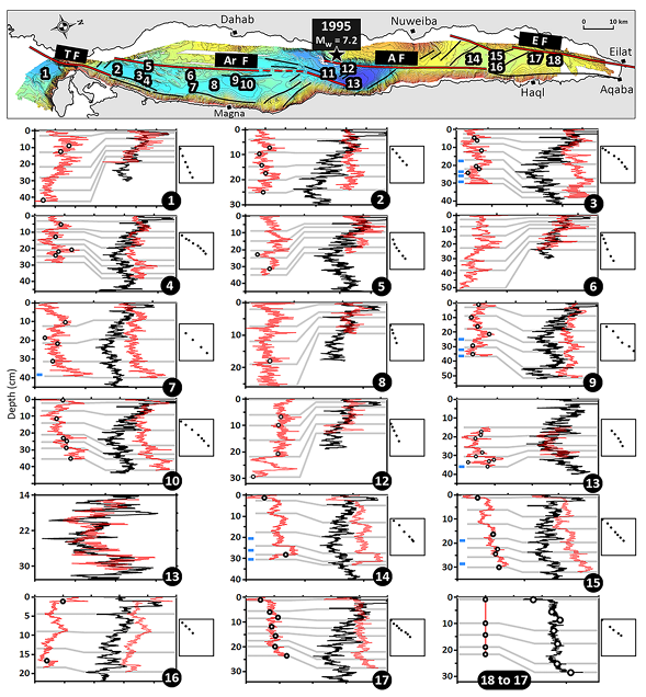
Fig. 4 shows radiographic images of all the 18 cores side-by-side along the gulf, together with the depths of 14C and 210Pb measurements and their results (Table in Fig. 4). The stratigraphic order of the dated samples confirms that our samples were collected in regular sedimentation sections and not in any anomalous sedimentary event. Radiocarbon results of 16 samples show that most of the cores include the sedimentary record for at least the last 1000 years.

We applied the “Constant Flux Constant Sedimentation Rate” model (Goldberg, 1963) on the 210Pbex (excess lead) from the cores 3, 7, and 17, which yielded sedimentation rates of 0.25, 0.19, and 0.38 mm/yr for the top parts of these cores, respectively. It should be noted that event 17-A was excluded from the depth scale for the sediment rate calculation of core 17. Although the number of radionuclide samples collected from core 7 is insufficient to achieve a statistically meaningful sedimentation rate, the 210Pbex results from cores 3 and 17 can be compared with the radiocarbon ages. For core 3, 14C at the bottom of the core yields a bulk sediment rate of 0.44 mm/yr, which is inconsistent with the rate obtained by 210Pbex for the same core (0.25 mm/yr). However, 14C-based sediment-rate calculation by using composite depths, which are obtained by excluding the sedimentary events, yields a composite sediment rate of 0.26 mm/yr that is consistent with the 210Pbex sediment rate. Similarly, 14C-based bulk rates for cores 14 and 15 (0.56 and 0.50 mm/yr, respectively) in Eilat Deep are much higher than the 210Pbex-based sediment rate obtained for core 17 (0.38 mm/yr) from the same basin. However, once corrected by removing the event layers, the 14C-based composite sediment rates for cores 14 and 15 (0.34 and 0.33 mm/yr, respectively) are rather consistent with the 0.38 mm/yr derived from the 210Pbex measurements. Thus, these two comparisons confirm the importance of determining both the bottom and top boundaries of sedimentary events to properly exclude them from the sequences and hence to construct reliable sediment chronology.

In order to cross-check the existence and extent of the sedimentary events in the cores, we compared our visual inspections of the radiographic images to magnetic susceptibility, grain-size (only sand content) and µ-XRF measurements (Fig. 5). For these analyses, at least one core per basin was selected. During floods or mass wasting events, coarser sediments originating from the shallower parts of the basin or from drainages onshore are expected to reach bottom of the basins. Thus, sand content in the event deposits is expected to increase compared to the background sedimentation. Deep marine sediments are normally a mixture of terrigenous clastics (mainly aluminosilicate minerals) and bio/chemical carbonates produced in the water column. However, there is almost no bio/chemical carbonate input during the almost instantaneous deposition of turbidite or flood deposits, which makes them richer in terrigenous clastics compared to the background sediments. Since aluminosilicates have higher magnetic susceptibility values than carbonates (Nowaczyk, 2001), turbidite and flood deposits should show as anomalies along the magnetic susceptibility profiles of the cores. Similarly, Zr/Sr profiles, where Zr and Sr represent aluminosilicates and foraminiferal calcite, respectively (Rothwell et al., 2006; Croudace and Rothwell, 2015), should show anomalies at turbidite and flood levels.

Among the 67 events shown in Fig. 5, significant magnetic susceptibility anomalies are observed for 51 of them. While 11 events (1-C, 3- D, 7-A, 9-C, 10-B, 10-C, 13-I, 15-C, 17-E, 17-G, and 18-B) show almost no magnetic susceptibility anomalies, only three events (3-A, 15-A, and 17-A) have clearly lower magnetic susceptibility values than the background sediments. Sand fraction profiles show distinct anomalies for 57 events out of 67. On the other hand, events 7-B, 15-A, 15-B, and 17-A have lower sand content compared to the background sediments. No sand anomalies are observed for four events (1-A, 1-B, 13-I, and 17-G). Since no µ-XRF scanning was done for core 18, 62 events can be tested for Zr/Sr anomalies. Among these, 49 events show higher and only two events (3-A and 17-A) lower Zr/Sr anomalies. Nine events (3-C, 3-D, 7-A, 9-C, 10-B, 11-A, 11-B, 13-D, and 13-I) show no Zr/Sr anomalies. Accordingly, from the data presented in Fig. 5, we note that magnetic susceptibility, sand content, and Zr/Sr profiles are successful in detecting sedimentary events observed on the radiographic images at rates of 81%, 91%, and 79%, respectively. Although Type I and Type III events are already evident in the radiographic images, some Type II events are unclear in the images (e.g., 7-A in Fig. 3). Magnetic susceptibility, sand content, and Zr/Sr profiles, together with the radiographic images, were therefore particularly useful to confirm/detect the thickness of Type II events, so that all sedimentary events were successfully excluded from the sequences covered by the cores to achieve reliable stratigraphical correlations and sediment chronology.

Chemostratigraphical correlation and sediment chronology

Coevality of turbidites at different locations and even in different basins should be tested to achieve successful submarine paleoseismological records (e.g., Goldfinger, 2011), which can be achieved by careful high-resolution stratigraphical correlations. In Fig. 4, some of the sedimentary events can be visually correlated between cores collected from the same basin according to their stratigraphical order, e.g., between the cores 2, 3, and 4 in Tiran basin, cores 9 and 10 in Dakar basin, and cores 14, 15, 16, 17 and 18 in Eilat basin. However, visual observations are not reliable enough for inter-basin correlations between the cores as one cannot assume that the number of turbidites in different basins is the same. Stratigraphical correlations between cores can be achieved by using data reflecting geophysical and geochemical properties of sediments, which may include magnetic susceptibility, bulk density, grain-size distribution, computed tomography (CT) image analysis, μ-XRF data and paleomagnetic secular variation (PSV) records (Patton et al., 2013; Drab et al., 2015; Ikehara et al., 2016; Goldfinger et al., 2017; Usami et al., 2018). In our study, geophysical and geochemical properties of sediments were evaluated by magnetic susceptibility and grain-size measurements (Sand percent), and μ-XRF μ scanning, of which resolutions were 5 mm, 10 mm and 0.5 mm, respectively. μ-XRF data, which has significantly higher resolution than the other proxies, was preferred for core correlation. Reliable chemostratigraphical correlations over large distances, like in our case where the cores are distributed along the ~180-km-long gulf, can only be successfully achieved by using a sedimentary geochemical proxy recording regional environmental conditions effective for the entire gulf. It is known that Sr/Ca ratios of planktonic foraminifera have a strong positive correlation with sea-surface temperature (e.g., Clerouxet al., 2008). Since the sediments of the Gulf of Aqaba are rich in planktonic foraminifera, and by assuming that the surface seawater temperatures would synchronously change over the entire gulf, we used Sr/Ca ratio profiles to correlate the cores in this study.

We intentionally collected core 11, the longest core in this study, from a ridge just to the south of the Aragonese Deep, rather than from the depocenter of the basin (Fig. 1d), so that it would dominantly reflect the background sedimentation recording the climatic conditions rather than being dominated by turbidites. To achieve reliable stratigraphical correlations, sedimentary events should be excluded from the sequences, and correlations should be done on composite profiles representing background sedimentation (Arnaud et al., 2002; Schwab et al., 2009; Avs¸ar et al., 2015; Moernaut et al., 2017). After excluding the sedimentary events, we correlated the composite Sr/Ca profiles of all the cores to the composite Sr/Ca profile of core 11 (Fig. 6). As the sedimentation rates are different between basins, this resulted in squeezing or stretching of the core records. This calibration was done using 5 to 8 characteristic reference levels that can be recognized in all the cores, which we used as tie-points to ensure consistency between the cores through the calibration process. (Gray lines in Fig. 6). Detailed explanation of the procedure for the removal of the sedimentary events and chemo-stratigraphical correlation can be found in Supplementary Material (E-SUPP 2). The original and modified depths of these tie-points are also presented as bi-plots next to each correlation plot in Fig. 6. Almost linear and smooth appearances of these bi-plots confirm that depth modifications did not result in abnormal sedimentation rates. For five cores (1, 6, 8, 12, and 13), the chemostratigraphical correlations result in almost perfect overlaps with core 11. For most of the other cores, although exact overlaps are not achieved, similarities between general trends and fluctuations along the cores are still within the range of uncertainties and thus are deemed acceptable. The discrepancies are probably due to the semi-quantitative nature of ITRAX µ-XRF scanning data or local differences in sedimentation. In addition, cores 11 and 13 were collected by a piston corer, which sometimes causes a disturbance and sediment loss close to the water/sediment interface. However, a good correlation between cores 11 and 12, which was taken by a multicorer ensuring undisturbed recovery of water/sediment interface, confirms that there was no sediment loss at the top of core 11. On the other hand, correlation between cores 11 and 13 shows that approximately 15 cm-thick sediment was lost at the top of core 13 during coring operation. A close-up view of the correlation between cores 13 and 11 is also provided in Fig. 6. Correlation between cores 17 and 18 is based on the stratigraphical order of the events since no µ-XRF data is available for core 18.

The raw 14C dates listed in Fig. 4 were included in the OxCal P_Sequence code (E-SUPP 3) with respect to their modified depths obtained by the chemostratigraphical correlations, as if all the radiocarbon samples came from core 11. The k value for the P_Sequence function was selected as 3, which is generally used for deep sea environments where hemipelagic sedimentation can be assumed rather constant (e.g., Polonia et al., 2023). Although the dates show a reasonable trend along core 11 (Fig. 7), two dates, the one from the bottom of core 7 (7–38.70) and the youngest date from core 9 (9–33.04), are clearly older than the general trend. Hence, we interpret them as reworked material and did not use them in the P_Sequence code. The resulting age-depth model, which is presented with 68% and 95% confidence intervals in Fig. 7, yields approximate sedimentation rates of 0.35, 0.16 and 0.22 mm/yr for the intervals of 0–32 cm, 32–55 cm and 55–80.5 cm, respectively. All of the sedimentary events projected on core 11 are also plotted with respect to depth in Fig.7, and are included in the P_Sequence code (E-SUPP 3), so that probability density functions (PDFs) for each event detected in Gulf of Aqaba can be calculated.

Discussion

PDFs of Type I and Type II events in the cores through the gulf are plotted with respect to calendar dates in Fig. 8, which were obtained according to the age-depth relation presented in Fig. 7. The probability density values for Type II events were multiplied by 0.5 since they may also be floods. Type III events, which are most probably not related to earthquakes, were not included in this plot. In Fig. 8, the plot of summed PDFs is also presented in order to statistically express the spatial extent and coevality of turbidites in the gulf; i.e., multiple coeval turbidites should be seen as distinct anomalies on the summed PDFs profile. Several sedimentary events appear to be coherent for several cores, including cores located in different basins. Hence, they are seen as anomalies in the summed PDFs profile (e.g., around late 10th, 16th and 20th centuries CE), and we interpret these events as the signature of past earthquakes that triggered turbidites (Type I or II) in the Gulf of Aqaba.

The turbidites dated to the late 20th century are unambiguously seen as Type I events at the tops of cores in Aragonese and Eilat Deeps (Cores 11, 12, 14, 15, 16, 17, and 18) and as Type II event in Dakar Deep (Core 10). They constitute a perfect benchmark of our sedimentary system as they are almost certainly the sedimentary traces of the 1995 Nuweiba (MW 7.2) earthquake, the most recent major earthquake in the Gulf of Aqaba. Given that the Aragonese Fault, and probably partially the Eilat Fault as well, were the source faults for the 1995 Nuweiba earthquake and that the earthquake rupture propagated northward (Baer et al., 2008; Hofstetter, 2003; Klinger et al., 1999; Shamir et al., 2003; Ribot et al., 2021), it is not surprising that turbidites (Type I events) from this earthquake are not found in cores from the southern part of the gulf (i.e., cores 1 to 10). Despite the proximity to the epicenter of the 1995 earthquake, no turbidite associated with this event is visible in core 13 due to sediment loss at the top of that core (Fig. 6).

Among older turbidites, two events stand out and are recognized almost in every core, one in about the early 12th century CE and one in about the late 16th century CE. Starting from the oldest turbidites, one series of turbidites are clearly visible as Type I events in all cores (except core 11), which are long enough to cover at least the last millennium (Fig. 8). Since core 11 is not a turbidite-targeting core, and it was collected from a ridge rather than from a depocenter, it can be expected to see only limited evidence for turbidites in this core. The significant anomaly on the summed PDFs profile, near the beginning of the 12th century CE is most probably associated with the only major earthquake known in the region during that period: the CE 1068 earthquake. The temporal discrepancies observed for dates of turbidites in some cores are most probably related to the difficulties of the inter-core chemostratigraphical correlations due to intense bioturbation in the sediments of the Gulf of Aqaba that can lead to small time shifts when it comes to estimate exact age of specific core sections. The 18 March 1068 Aqaba-Hijaz earthquake was reported to have devastating effects in many locations from the city of Aila (Eilat) to Medina and Cairo (Ambraseys, 2009). Presence of seismo-turbidites all along the gulf in addition to evidence found at the onshore paleoseismic sites north of the Gulf (Amit et al., 1999, 2002; Zilberman et al., 2005; Klinger et al., 2015; Kanari et al., 2020) indicate that the CE 1068 earthquake was a major earthquake in the region that ruptured the Eilat, Aragonese, Arnona and probably Tiran faults together, in addition to the southernmost part of the Wadi Arabah Fault near the gulf. Hence, the total rupture length of this earthquake could have been at least ~200 km.

Similar as for the CE 1068 event, numerous coeval turbidites along the Gulf of Aqaba are represented by the anomaly on the summed PDFs profile about late 16th century CE, which is consistent with the well-documented earthquake of 4 January 1588 (Ambraseys, 2009). Majority of them are of Type I events, except the ones in core 2 in Tiran Deep, and in cores 9 and 10 in Dakar Deep, which are of Type II. The absence of turbidites in core 6 can be explained by the fact that this core was collected from a small and isolated basin (Fig. 1e). Indeed, this basin is isolated from turbidity flows that would come from the main slopes of the gulf, and its relatively smaller slopes may not be sensitive to earthquake shaking as much as the larger main slopes of the gulf. An absence of a turbidite in core 14 is more difficult to explain. One possible explanation could be the sediment clearance on the slopes and the banks of the submarine channels during the preceding earthquake, i.e., in CE 1068, leaving nothing to be wasted during the CE 1588 earthquake. Furthermore, another possibility is that the turbidity flows due to 1588 earthquake might have bypassed the location of core 14 (Goldfinger et al., 2017). Apart from turbidite absence in these three cores, it seems that the CE 1588 earthquake triggered seismo-turbidites along the entire gulf. This earthquake is also known as a devastating event in the historical records, affecting many places from the cities of Eilat and Aqaba at the northern end of the gulf to Cairo in Egypt (Ambraseys, 2009). A second event is also reported in the historical chronicles that happened on 7 April 1588, which was felt in Cairo and in the northern Red Sea. Although it cannot be ruled out that this second event was completely independent of the event in January 1588, it could be an aftershock of the former event (Ambraseys, 2009), triggering additional turbidites for example along the Tiran fault section. Klinger et al. (2015) report no surface rupturing evidence for the CE 1588 earthquake at the Qatar trench site (x in Fig. 1b). On the other hand, Kanari et al. (2020) report both rupturing and paleoliquefaction evidences that could be related to this earthquake in the Eilat Sabkha (t in Fig. 1b). Hence, based on our seismo-turbidite observations, it appears that the CE 1588 earthquake likely also ruptured the entire fault system in the Gulf of Aqaba. Unlike in CE 1068, however, the 1588 rupture does not seem to have propagated inland beyond the northern end of the gulf. In the south, based on turbidites we can trace the rupture to the south of the Tiran Strait and it may have ruptured even further to the south.

Some additional sequences of turbidites are found in our record, although they are not as extensive as the sequences associated respectively to the CE 1068 and CE 1588 earthquakes. According to the historical records, the CE 1212 earthquake caused widespread damage in an extensive area from Al-Shaubak and Al-Karak in the north (ca. 150 km north of Eilat and Aqaba cities) to the St. Catherine Monastery in the south (ca. 50 km east of Dahab) (Ambraseys, 2009). Although Klinger et al. (2015) reported evidence of surface rupturing along the southern Wadi Arabah Fault (Qatar Site, x in Fig.1b) that could be related to the CE 1212 earthquake, the trenching studies closer to the gulf (Zilberman et al., 2005; Kanari et al., 2020; y and t in Fig. 1b, respectively) claim that the CE 1212 earthquake was likely generated by a secondary fault on the eastern edge of the Eilat depression, rather than by the Wadi Arabah Fault. The probable turbidites of the CE 1212 earthquake are only seen in cores 17 and 18 from the northernmost part of the gulf (Fig. 8). Thus, it appears as a minor anomaly in the summed PDFs profile. The turbidite in core 18 is thicker and better preserved with its laminated internal structure. Furthermore, there are no turbidites in cores 14 and 15 around 1200s. Given the absence of consistently coeval turbidites through the gulf that are dated to the beginning of the 13th century (except the one in core 13), and only two turbidites in the northernmost cores (17 and 18), we conclude that the CE 1212 earthquake was likely significantly smaller than the CE 1068 and CE 1588 events. The exact location of this event north of the gulf remains uncertain, but it might have caused a discontinuous rupture on fault segments of the Wadi Arabah Fault system.

Prominent turbidites with well-preserved internal structures are seen around the mid-19th century CE in cores 2, 3 and 4. No turbidites were found around this period in the neighboring cores, except Type II events in cores 1, 7, and 8. The summed PDFs profile has a minor anomaly due to these turbidites that are limited to the most southern part of the gulf. These turbidites are probably related to the CE 1839 earthquake, which is described in the historical records as causing minor damage on the walls of St. Catherine Monastery (Ambraseys, 2009). Furthermore, Purkis et al. (2022b) reported an incipient submarine landslide on the southeastern slopes of Tiran Deep that failed within the last 500 years, plausibly triggered by the CE 1839 earthquake. Given that the turbidites in cores 2, 3, and 4 are limited only in Tiran Deep, it is likely that the CE 1839 earthquake only partially ruptured either the Tiran or Arnona fault, or activated one of the secondary faults in the southernmost part of the gulf. Except for the ones related to the CE 1839 earthquake, the absence of distinct coeval turbidites in cores 1 to 10 (southern half of the gulf) since CE 1588 implies that most of the Tiran and Arnona faults has not ruptured since then.

While the cores provide a detailed record for the past millennium, only a few cores provide information for earlier periods. Around the middle 5th century CE, there are implications of coeval turbidites in cores 9, 10, and 11 in Dakar and Aragonese basins. Klinger et al. (2015) report evidence of surface rupturing at the Qatar trenching site on the Wadi Arabah Fault between 9 BCE and CE 492 (Fig. 8), which they attribute to the CE 363 earthquake that affected significantly the southern part of the Dead Sea Fault (Thomas et al., 2007; Ambraseys, 2009). However, this event could not be found north of the Qatar site (Lefevre et al., 2018). Hence, the turbidites around the middle 5th century CE could be due to a large earthquake rupturing several faults in the gulf, in addition to a 50 km long on-shore fault section. In core 11, three more Type I events, which can be other earthquakes in the gulf, are dated to ca. 250, 850 and 1350 BCE. The one around 250 BCE temporally correlates well with the event between 338 and 213 BCE, detected by Klinger et al. (2015) (Fig. 8). Although Klinger et al. (2015) do not report any event around 850 BCE, they report two events occurred during the period 2797–1245 BCE, which also coincide with the date of the turbidite ca. in 1350 BCE.

From the oldest turbidite to the youngest in 1995, the recurrence intervals for major earthquakes in the gulf seem to vary between 400 and 700 years (Fig. 8), with a mean value of 560 years. According to the paleoseismic trenching studies conducted in the north of the Gulf of Aqaba region, the Dead Sea Fault is characterized by earthquake clusters lasting 100–200 years, followed by seismic quiescence periods of 350–400 years (Klinger et al., 2015; Lefevre et al., 2018). On the other hand, Lefevre et al. (2018) have proposed that recurrence intervals for events should be longer due to partial stress partitioning between offshore and on-land fault segments, which is consistent with the 560 years recurrence interval found in the Gulf of Aqaba. In addition, the left-lateral relative plate motion between the Sinai and Arabian plates at this latitude is almost 5 mm/year (Castro-Perdomo et al., 2022; Viltres et al., 2022), which yields about 2 to 3.5 m fault slip deficit in a 400–700 year period, corresponding to an expected surface rupture length of 100–180 km (Wells and Coppersmith, 1994), which would be consistent with multi-segment rupturing events in the gulf. However, recent studies based on InSAR and GNSS observations (Li et al., 2021; Castro-Perdomo et al., 2022) report fault-locking depths that become shallower towards the south and possibility of partial fault creep along the southernmost fault strands of the gulf. Still, our results indicate that the entire Gulf of Aqaba fault system was activated in the 1068 and 1588 earthquakes and probably during the previous major earthquakes. This implies that the southern gulf can be regarded as being close to the end of the earthquake cycle as it has not ruptured in a major earthquake for more than 400 years.

Conclusions

Based on ITRAX µ-XRF scanning, radiographic imaging, magnetic susceptibility measurements and grain-size measurements, we detected a total of 86 sedimentary events in 18 sediment cores collected from the Gulf of Aqaba. Of these events, 46 were classified as distinct turbidites, 9 events described as thick flooding sequences due to high precipitation periods lasting probably several decades, and the remaining 31 less distinct events as turbidites or floods. Careful chemostratigraphical inter-core correlations and radiometric dating of these events provide a robust submarine paleoseismic record for the last millennium. The results show that the historical earthquakes in 1068 and CE 1588 were major characteristic earthquakes in the gulf that probably ruptured all the main faults (Tiran, Arnona, Aragonese and Eilat faults) in the gulf. On the other hand, the historical earthquakes of 1839 and CE 1212 were smaller and triggered only local turbidites in the southernmost and northernmost parts of the gulf, respectively. Information on older major events, together with the 1068 and CE 1588 earthquakes, suggests a recurrence interval of 400–700 years (average = 560 years), indicating that the southern gulf is a ripe for a major earthquake.

Fig. 2 - Radiographic Images of Type I events (prominent and well-preserved turbidites)

Normal Size

Fig. 2

U-channel radiographic images of prominent and well-preserved turbidites (Type I; red bars) in the sediments of the Gulf of Aqaba. Note the bioturbation and biogenic content (e.g., carbonaceous shells seen as whitish spots) in the background sedimentation. Event labeling is given in the lower left of each image.

Bektaş et al. (2024)

Magnified

Fig. 2

U-channel radiographic images of prominent and well-preserved turbidites (Type I; red bars) in the sediments of the Gulf of Aqaba. Note the bioturbation and biogenic content (e.g., carbonaceous shells seen as whitish spots) in the background sedimentation. Event labeling is given in the lower left of each image.

Bektaş et al. (2024)

Fig. 3 - Radiographic Images of Events of Types I (turbidites), II (turbidites or flood deposits), and III (flood deposits)

Normal Size

Fig. 3

U-channel radiographic images of different types of sedimentary events.
  • Type I: Turbidites (red bars)
  • Type II: Turbidite or Flooding (gray bars)
  • Type III: Thick Flooding Sequence (yellow bars)
Bektaş et al. (2024)

Magnified

Fig. 3

U-channel radiographic images of different types of sedimentary events.
  • Type I: Turbidites (red bars)
  • Type II: Turbidite or Flooding (gray bars)
  • Type III: Thick Flooding Sequence (yellow bars)
Bektaş et al. (2024)

Fig. 4 - Sedimentary Events detected in all cores

Normal Size

Fig. 4

Sedimentary events detected in the radiographic images of the Gulf of Aqaba cores, labelled by letters and indicated by red, gray, and yellow vertical bars. Depths of 210Pb and 14C measurements are also shown by green and blue rectangles next to the images, respectively. In the table, raw and calibrated 14C results are listed. The raw and composite depths, and the depths corresponding on core 11 (after stratigraphical correlation) for each 14C sample are also given. In the lower right, results of 210Pbex measurements on cores 3, 7, and 17 and the corresponding sedimentation rates (SR) are presented.

Bektaş et al. (2024)

Magnified

Fig. 4

Sedimentary events detected in the radiographic images of the Gulf of Aqaba cores, labelled by letters and indicated by red, gray, and yellow vertical bars. Depths of 210Pb and 14C measurements are also shown by green and blue rectangles next to the images, respectively. In the table, raw and calibrated 14C results are listed. The raw and composite depths, and the depths corresponding on core 11 (after stratigraphical correlation) for each 14C sample are also given. In the lower right, results of 210Pbex measurements on cores 3, 7, and 17 and the corresponding sedimentation rates (SR) are presented.

Bektaş et al. (2024)

Fig. 5 - Core Logs

Normal size

Fig. 5

Magnetic susceptibility (MS), sand content, and Zr/Sr profiles produced along selected cores (at least one core per basin) through the Gulf of Aqaba. Sedimentary events shown in Fig. 4 are also shown as horizontal bars in this figure. Event labeling and color code for different types of events are the same as in Fig. 4. See the Supplementary Material (E-SUPP 1) for detailed descriptions of sedimentary events for all of the cores.

Bektaş et al. (2024)

Magnified

Fig. 5

Magnetic susceptibility (MS), sand content, and Zr/Sr profiles produced along selected cores (at least one core per basin) through the Gulf of Aqaba. Sedimentary events shown in Fig. 4 are also shown as horizontal bars in this figure. Event labeling and color code for different types of events are the same as in Fig. 4. See the Supplementary Material (E-SUPP 1) for detailed descriptions of sedimentary events for all of the cores.

Bektaş et al. (2024)

Fig. 6 - Chemostratigraphical correlations

Normal Size

Fig. 6

Chemostratigraphical correlation of composite Sr/Ca ratio profiles (event-free) of each core (red curves) to core 11 (black curves). Depths of sedimentary events and radiocarbon dates are shown as dots and blue rectangles, respectively. Bi-plots next to each graph show the original composite depths (y-axes) versus the modified depths on core 11 (x-axes) of the tie-lines (gray lines). Details of the chemostratigraphical correlation procedure are presented in the Supplementary Material (E-SUPP 2).

Bektaş et al. (2024)

Magnified

Fig. 6

Chemostratigraphical correlation of composite Sr/Ca ratio profiles (event-free) of each core (red curves) to core 11 (black curves). Depths of sedimentary events and radiocarbon dates are shown as dots and blue rectangles, respectively. Bi-plots next to each graph show the original composite depths (y-axes) versus the modified depths on core 11 (x-axes) of the tie-lines (gray lines). Details of the chemostratigraphical correlation procedure are presented in the Supplementary Material (E-SUPP 2).

Bektaş et al. (2024)

Fig. 7 - Age-Depth Model

Normal Size

Fig. 7

Calibrated radiocarbon dates, and the age-depth model determined by OxCal P_Sequence function. Two reworked samples (9–33.04 and 7–38.70) were not included in the P_Sequence code, which can be found in the Supplementary Material (E-SUPP 3). The list and depths of all sedimentary events are also shown.

Bektaş et al. (2024)

Magnified

Fig. 7

Calibrated radiocarbon dates, and the age-depth model determined by OxCal P_Sequence function. Two reworked samples (9–33.04 and 7–38.70) were not included in the P_Sequence code, which can be found in the Supplementary Material (E-SUPP 3). The list and depths of all sedimentary events are also shown.

Bektaş et al. (2024)

Fig. 8 - Probability Distribution Functions (PDFs) of Type I and Type II events along the Gulf of Aqaba

Normal Size

Fig. 8

Plot of Probability Distribution Functions (PDFs) of Type I and Type II events along the Gulf of Aqaba. Horizontal black lines mark the dates of historical earthquakes in the region. Major earthquakes that triggered extensive turbidites all along the gulf are seen as major anomalies on the summed PDFs profile. The scale of x-axis changes around CE 800. Time windows for the prehistorical surface rupturing events at the Qatar trenching site (x in Fig. 1, Klinger et al., 2015) are also shown. Note the recurrence intervals varying between 400 and 700 years and also the absence of extensive coeval turbidites in the southern half of the gulf since CE 1588.

Bektaş et al. (2024)

Magnified

Fig. 8

Plot of Probability Distribution Functions (PDFs) of Type I and Type II events along the Gulf of Aqaba. Horizontal black lines mark the dates of historical earthquakes in the region. Major earthquakes that triggered extensive turbidites all along the gulf are seen as major anomalies on the summed PDFs profile. The scale of x-axis changes around CE 800. Time windows for the prehistorical surface rupturing events at the Qatar trenching site (x in Fig. 1, Klinger et al., 2015) are also shown. Note the recurrence intervals varying between 400 and 700 years and also the absence of extensive coeval turbidites in the southern half of the gulf since CE 1588.

Bektaş et al. (2024)

Individual Core Logs

Core 1

E-SUPP 1

Radiographic images, magnetic susceptibility, sand content and Zr/Sr profiles of Aqaba cores, together with sedimentary event descriptions

Bektaş et al. (2024) Supplemental

Core 2

E-SUPP 1

Radiographic images, magnetic susceptibility, sand content and Zr/Sr profiles of Aqaba cores, together with sedimentary event descriptions

Bektaş et al. (2024) Supplemental

Core 3

E-SUPP 1

Radiographic images, magnetic susceptibility, sand content and Zr/Sr profiles of Aqaba cores, together with sedimentary event descriptions

Bektaş et al. (2024) Supplemental

Core 4

E-SUPP 1

Radiographic images, magnetic susceptibility, sand content and Zr/Sr profiles of Aqaba cores, together with sedimentary event descriptions

Bektaş et al. (2024) Supplemental

Core 5

E-SUPP 1

Radiographic images, magnetic susceptibility, sand content and Zr/Sr profiles of Aqaba cores, together with sedimentary event descriptions

Bektaş et al. (2024) Supplemental

Core 6

E-SUPP 1

Radiographic images, magnetic susceptibility, sand content and Zr/Sr profiles of Aqaba cores, together with sedimentary event descriptions

Bektaş et al. (2024) Supplemental

Core 7

E-SUPP 1

Radiographic images, magnetic susceptibility, sand content and Zr/Sr profiles of Aqaba cores, together with sedimentary event descriptions

Bektaş et al. (2024) Supplemental
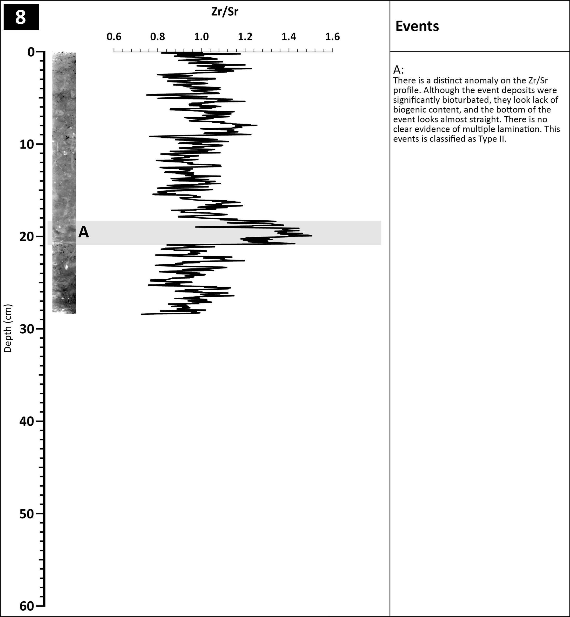
Core 8

E-SUPP 1

Radiographic images, magnetic susceptibility, sand content and Zr/Sr profiles of Aqaba cores, together with sedimentary event descriptions

Bektaş et al. (2024) Supplemental

Core 9

E-SUPP 1

Radiographic images, magnetic susceptibility, sand content and Zr/Sr profiles of Aqaba cores, together with sedimentary event descriptions

Bektaş et al. (2024) Supplemental

Core 10

E-SUPP 1

Radiographic images, magnetic susceptibility, sand content and Zr/Sr profiles of Aqaba cores, together with sedimentary event descriptions

Bektaş et al. (2024) Supplemental

Core 11a

E-SUPP 1

Radiographic images, magnetic susceptibility, sand content and Zr/Sr profiles of Aqaba cores, together with sedimentary event descriptions

Bektaş et al. (2024) Supplemental

Core 11b

E-SUPP 1

Radiographic images, magnetic susceptibility, sand content and Zr/Sr profiles of Aqaba cores, together with sedimentary event descriptions

Bektaş et al. (2024) Supplemental

Core 12

E-SUPP 1

Radiographic images, magnetic susceptibility, sand content and Zr/Sr profiles of Aqaba cores, together with sedimentary event descriptions

Bektaş et al. (2024) Supplemental

Core 13a

E-SUPP 1

Radiographic images, magnetic susceptibility, sand content and Zr/Sr profiles of Aqaba cores, together with sedimentary event descriptions

Bektaş et al. (2024) Supplemental

Core 13b

E-SUPP 1

Radiographic images, magnetic susceptibility, sand content and Zr/Sr profiles of Aqaba cores, together with sedimentary event descriptions

Bektaş et al. (2024) Supplemental

Core 14

E-SUPP 1

Radiographic images, magnetic susceptibility, sand content and Zr/Sr profiles of Aqaba cores, together with sedimentary event descriptions

Bektaş et al. (2024) Supplemental

Core 15

E-SUPP 1

Radiographic images, magnetic susceptibility, sand content and Zr/Sr profiles of Aqaba cores, together with sedimentary event descriptions

Bektaş et al. (2024) Supplemental

Core 16

E-SUPP 1

Radiographic images, magnetic susceptibility, sand content and Zr/Sr profiles of Aqaba cores, together with sedimentary event descriptions

Bektaş et al. (2024) Supplemental

Core 17

E-SUPP 1

Radiographic images, magnetic susceptibility, sand content and Zr/Sr profiles of Aqaba cores, together with sedimentary event descriptions

Bektaş et al. (2024) Supplemental

Core 18

E-SUPP 1

Radiographic images, magnetic susceptibility, sand content and Zr/Sr profiles of Aqaba cores, together with sedimentary event descriptions

Bektaş et al. (2024) Supplemental
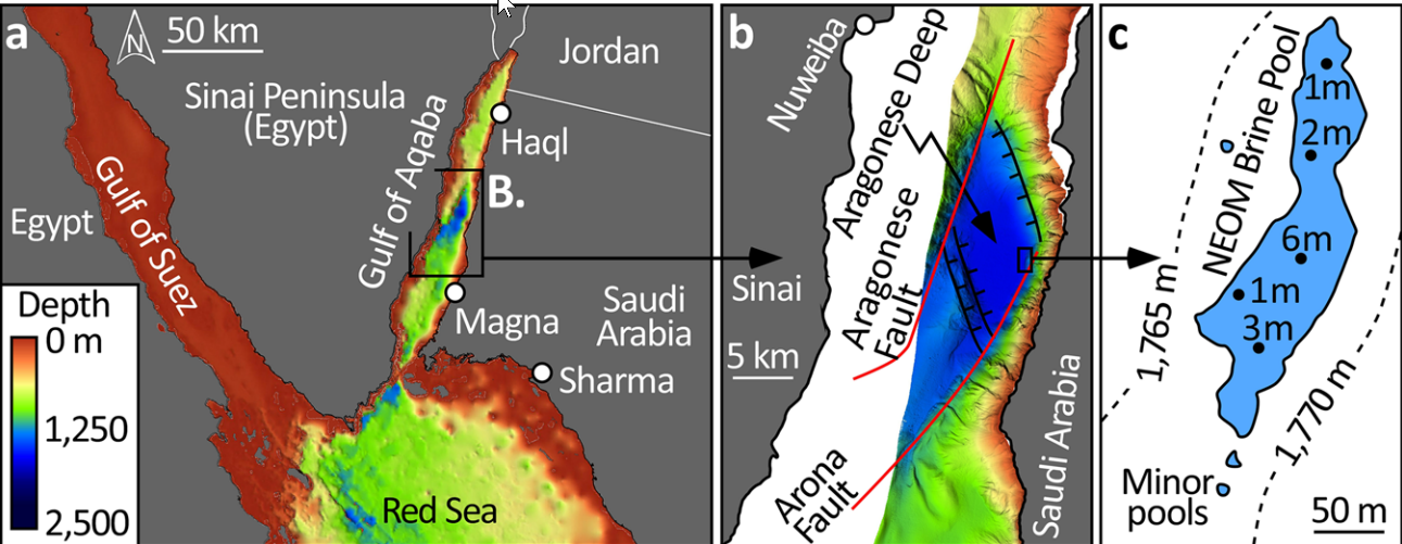
R/V OceanXplorer

NEOM Brine Pools

Location Map

Fig. 3

Bathymetric and tectonic setting of the NEOM Brine Pools in the Gulf of Aqaba.
  1. The General Bathymetric Chart of the Oceans (GEBCO) provides regional context to the multibeam data acquired during the OceanX-NEOM research cruise.

  2. The brine pool is located at the toe-of-slope of the Saudi coastal margin in the Aragonese Deep, a pull-apart basin and the deepest point in the Gulf. This basin is bounded by the strike-slip Arona and Aragonese faults (red lines), which connect via normal faults (black lines). The NEOM pools are situated at the junction between the coast-parallel Arona Fault and the NNW-trending normal fault that demarcates the northern margin of the basin.

  3. The brine-seawater interface is at 1770 m depth, and the main pool is 260 m long, 70 m wide, and covers an area of 10,000 m2 (large blue polygon). Echo soundings (black dots) indicate a maximum brine thickness of 6 m in the center of the pool. Three minor pools, each <10 m2 in area, were discovered within 50 m of the main pool: one westward and two southward (small blue polygons).

Click on image to open in a new tab

Purkis et al. (2022b)
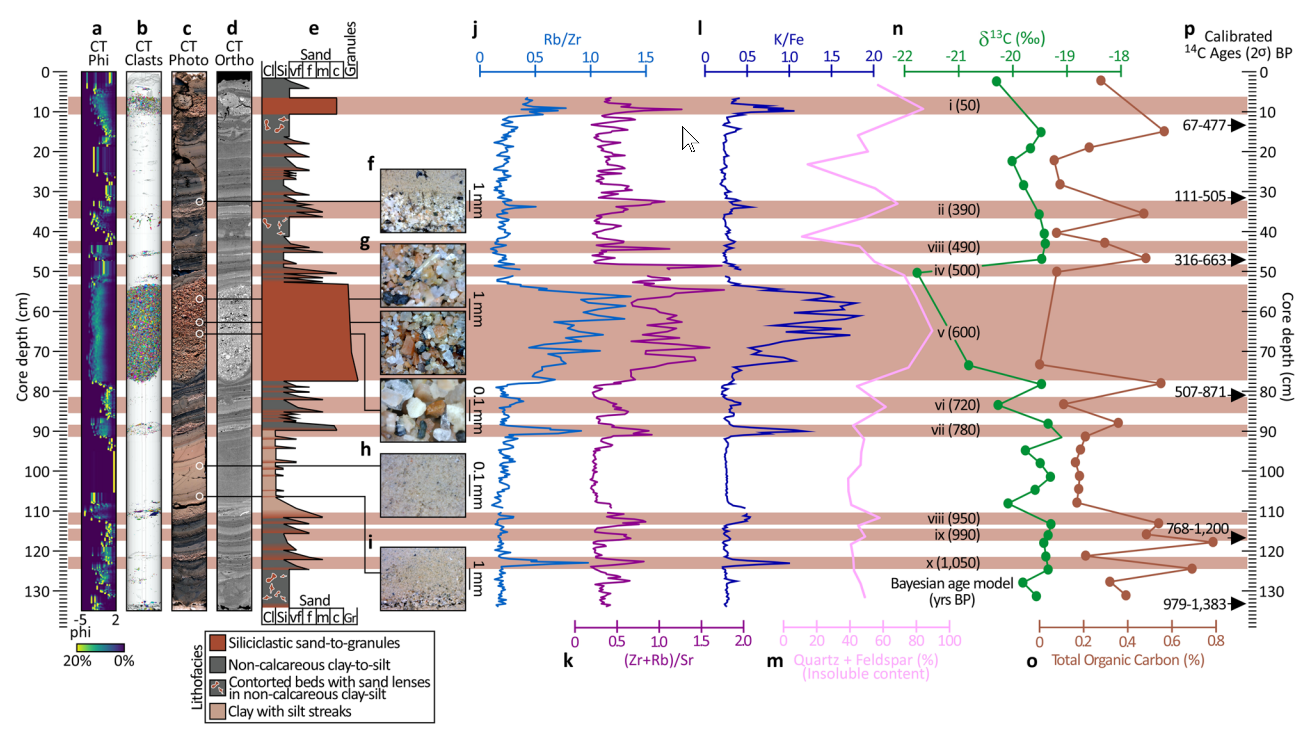
Cores

Fig. 8

Litho- and chemostratigraphy of the 150-cm-long core (Core #5) from the main NEOM Brine Pool.
  1. Clast size analysis derived from computed tomography (CT) scanning of the core. In this histogram plot, the left border is −5 phi (i.e., coarse clasts) and the right border is 2 phi (fine clasts). The color scale varies from 0% occurrence of a given phi in 1 cm intervals in blue, up to 20% by volume in yellow.

  2. Using random colors, individual clasts are identified. This 3-D visualization excellently emphasizes the ten conspicuous coarse-grained siliciclastic turbidite intervals. Of these, the most prominent is 'v' at 54–77 cm core depth, which dates to ∼600 yrs. BP.

  3. A high-resolution digital photo-scan of the split core.

  4. The equivalent grayscale orthoslice reconstructed from CT.

  5. The core description capturing grain size and lithofacies.

  6. Photomicrographs detail the fining-upwards arrangement of the turbidite deposits, including coarse siliciclastic intervals, the clay deposit with silt streaks during times of uninterrupted deposition, and interspersed fining-upwards turbidite deposits.

  7. The chemostratigraphy of the core is captured by variation of elemental intensities measured by XRF-scanning and presented as three ratios: Rb/Zr, (Zr + Rb)/Sr, and K/Fe, along with the combined abundance of quartz and feldspar.

  8. These traces are supplemented with discrete analyses of 27 samples for carbon stable isotope (δ13C) and total organic carbon.

  9. 14C ages calibrated to calendar yrs. BP with 2σ error reported.

Click on image to open in a new tab

Purkis et al. (2022b)
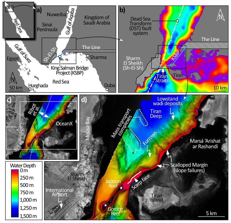
Tiran Straits

Location Map

Fig. 1

Location of the study area in the Tiran Straits, tectonic setting, and bathymetry:
  1. The strike-slip Dead Sea Transform (DST) fault system (white dot-dash line in b) runs along the axis of the Straits and is composed of several systematically offset, overlapping, left-lateral transform faults. Local infrastructure includes the Egyptian town of Sharm El Sheikh (approx. city limits, hatched polygon in a and b), and planned construction of “The Line,” a 170 km-long east-west-trending city (hatched rectangle in b), and the King Salman Bridge Project which would straddle Tiran Island (blue line in a-b, position approximate).
  2. Multibeam bathymetry created by merging data from Ribot et al. (2021), west of the broken white line in (c), with that acquired by OceanX (east of broken white line).
  3. Enlarges the bathymetry offshore Sharm El Sheikh including the location of the scarp face and two instances of slope failure to the north of it, recognized by the paired occurrences of scallop “bite” marks in the eastern margin of the Straits with mass-transport complexes (delimited by broken white lines) lying outboard of them on the abyssal plain of the Tiran Deep. Submersible dive (black asterisk) on the southernmost complex confirmed abundant breccia blocks. Margin-perpendicular furrows are evident on areas of the slope that have failed, likely excavated by cascading density currents. To the northeast of the two paleo-slope failures, canyon heads at the shelf break have been fed by wadis during sea-level lowstands, delivering substantial deposits to the abyssal plain.

Click on image to open in a new tab

Purkis et al. (2022a)
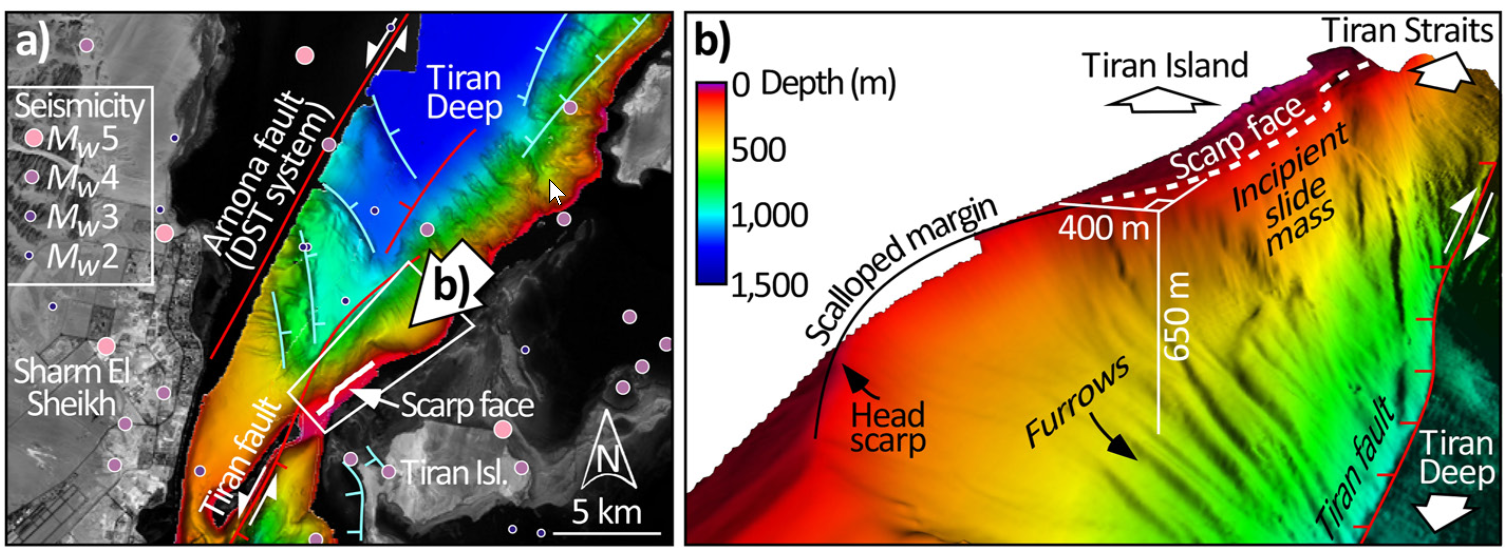
Seismo-Tectonic Setting

Fig. 2

Seismotectonic setting of the Tiran Straits and southern Gulf of Aqaba:
  1. Shows the main active faults in the vicinity of the Straits (modified from Goldberg & Beyth, 1991 and from Ribot et al., 2021) and Mw ≥ 2 earthquakes for the period 1970–2021 (U.S. Geological Survey). Strike-slip faults are in red. Both the Tiran and Arnona faults are part of the strike-slip Dead Sea Transform (DST) fault system (Figure 1b). Normal faults are in cyan. The area in the white polygon is shown in three dimensions in (b).
  2. Here, vertical exaggeration is ×2.5 and the observer is looking from the northeast, along the Saudi margin of the Gulf of Aqaba, toward the Straits. The scarp face (broken white line) situates immediately adjacent to a scallop which demarks a previous margin failure. We interpret the slide mass from the incipient failure which generated the scarp to extend down-slope to a water depth of 650 m. The toe-of-slope beneath this mass is at 850 m depth and bounded by the Tiran fault.

Click on image to open in a new tab

Purkis et al. (2022a)
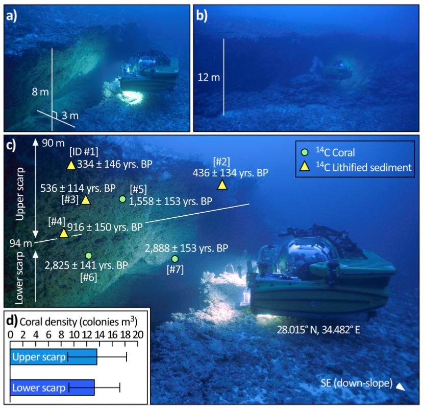
Scarp Face

Fig. 3

Radiocarbon dates and distribution of biota on the scarp face:
  1. Representative photograph of the scarp. The sub is facing southeast, into the scarp, toward Tiran Island. The abyssal depths of the Tiran Deep are therefore aft of the sub in this photograph. The scarp has both a vertical and lateral offset, which at this location measures 8 and 3 m, respectively.
  2. Representative photograph of the scarp acquired ∼50 m back from the scarp. The sub is facing southeast, into the scarp, toward Tiran Island. The abyssal depths of the Tiran Deep are therefore aft of the sub. The vertical offset here attains 12 m, approaching the maximum vertical offset of 15 m encountered along the 6 km strike of the feature.
  3. Either corals, or the (now lithified) sediments infilling their skeletons, were isolated from each rock sample extracted from the scarp and 14C dated. Ages calibrated to calendar years BP (before present) with 2 sigma error reported. Sample IDs in square brackets reference Table S1 in Supporting Information S1. Corals range in age from 2,888 years to 1,558 years BP. Lithified sediments are younger, ranging from 916 years to 334 years BP. White line divides the scarp into upper (90–94 m water depth) and lower (94–98 m) units where mean density (±std) of coral colonies was quantified (d).
  4. The densities are not significantly different (p > 0.05), implying the scarp was created swiftly by a single event.

Click on image to open in a new tab

Purkis et al. (2022a)

Environmental Effects (ESI 2007)

Graphic Representation of ESI 2007 Intensity

click on image to open a higher resolution version in a new tab

Master Seismic Events Tables
R/V Thuwal and R/V Mediterranean Explorer Cores

  • R/V Thuwal and R/V Mediterranean Explorer Cores are in different tabs

Paleo-Debris Flow Chronology
Two Mass Flow Events in R/V Mediterranean Explorer cores P12, P17, P22 and/or P29 - ~38000 BCE

Location Map and Core Logs

Location Map and Core Logs

Location Map

Elat Cores Fig. 1

(a) Regional tectonic map of the Dead Sea Transform and location of the Gulf of Aqaba/Elat

(b) Topographic image map of the southern Arava Valley showing location of the study area of the Elat Sabkha. Previously mapped faults in black lines (after Garfunkel, 1970; Garfunkel et al., 1981; Sneh et al., 1998). Previous study sites including Avrona Sabkha and Yovata Sabkha and locations of the paleoseismic trenches (in block circles)
  • QT = Qatar trench (Klinger et al., 2015)
  • AT = Avrona Trenches (Amit et al., 1999; Zilberman et al., 2005)
  • ST = Shehoret trenches (e.g. Amit et al., 2002)
  • GAE = Gulf of Aqaba/Elat

CMP shots discussed in this study from seismic lines SI-4047 and GI-2108 are plotted as light-blue dots and yellow dots, respectively. The blue rectangle marks the extent of the study area maps presented in Figs. 3 and 9. The pink line represents the location of the offshore high-resolution seismic profile by Hartman et al. (2014) detailed in Fig. 2b.

Kanari et al (2020)

Core Logs from P17, P22, and P29

Elat Cores Figure 5

Grain size distribution (downcore spectrum of % volume per grain diameter) of cores P17 (540 mbsl), P22 (316 mbsl) and P29 (282 mbsl) from the Northern Gulf of Aqaba-Elat; see Fig. 2 for core locations

Kanari et al (2015)

Discussion
Discussion

References
Notes by JW

Kanari et al (2015) examined several R/V Mediterranean Explorer cores - P12, P17, P22 and P29 (460, 540, 320 and 280 mbsl) for coarse grain anomalous events. Ages were determined using radiocarbon dating of foraminifera, gastropod and bivalves. They came to the following conclusions:

For some events, more than one anomalous events appear to coincide in time in different cores. We suggest that where anomalous events in different cores coincide in their age constraints – it is most likely evidence for mass flow triggered by earthquake events, driving coarse material from the shallower shelf edge into the deep basin (as opposed to sporadic slumping, or mass flow triggered by flashfloods).
Kanari et al (2015) dated two events to ~38000 BCE (40 ka) although they cautioned that the limits of radiocarbon dating for this age results in uncertainty and reduced confidence.

Mass Flow Event in R/V Mediterranean Explorer cores P12, P17, P22 and/or P29 - ~12500-12000 BCE

Location Map and Core Logs

Location Map and Core Logs

Location Map

Elat Cores Fig. 1

(a) Regional tectonic map of the Dead Sea Transform and location of the Gulf of Aqaba/Elat

(b) Topographic image map of the southern Arava Valley showing location of the study area of the Elat Sabkha. Previously mapped faults in black lines (after Garfunkel, 1970; Garfunkel et al., 1981; Sneh et al., 1998). Previous study sites including Avrona Sabkha and Yovata Sabkha and locations of the paleoseismic trenches (in block circles)
  • QT = Qatar trench (Klinger et al., 2015)
  • AT = Avrona Trenches (Amit et al., 1999; Zilberman et al., 2005)
  • ST = Shehoret trenches (e.g. Amit et al., 2002)
  • GAE = Gulf of Aqaba/Elat

CMP shots discussed in this study from seismic lines SI-4047 and GI-2108 are plotted as light-blue dots and yellow dots, respectively. The blue rectangle marks the extent of the study area maps presented in Figs. 3 and 9. The pink line represents the location of the offshore high-resolution seismic profile by Hartman et al. (2014) detailed in Fig. 2b.

Kanari et al (2020)

Core Logs from P17, P22, and P29

Elat Cores Figure 5

Grain size distribution (downcore spectrum of % volume per grain diameter) of cores P17 (540 mbsl), P22 (316 mbsl) and P29 (282 mbsl) from the Northern Gulf of Aqaba-Elat; see Fig. 2 for core locations

Kanari et al (2015)

Discussion
Discussion

References
Notes by JW

Kanari et al (2015) examined several R/V Mediterranean Explorer cores - P12, P17, P22 and P29 (460, 540, 320 and 280 mbsl) for coarse grain anomalous events. Ages were determined using radiocarbon dating of foraminifera, gastropod and bivalves. They came to the following conclusions:

For some events, more than one anomalous events appear to coincide in time in different cores. We suggest that where anomalous events in different cores coincide in their age constraints – it is most likely evidence for mass flow triggered by earthquake events, driving coarse material from the shallower shelf edge into the deep basin (as opposed to sporadic slumping, or mass flow triggered by flashfloods).
Kanari et al (2015) dated one of the events to ~12500-12000 BCE (14.0-14.5 ka)

Mass Flow Event in R/V Mediterranean Explorer cores P12, P17, P22 and/or P29 - ~5550 BCE

Location Map and Core Logs

Location Map and Core Logs

Location Map

Elat Cores Fig. 1

(a) Regional tectonic map of the Dead Sea Transform and location of the Gulf of Aqaba/Elat

(b) Topographic image map of the southern Arava Valley showing location of the study area of the Elat Sabkha. Previously mapped faults in black lines (after Garfunkel, 1970; Garfunkel et al., 1981; Sneh et al., 1998). Previous study sites including Avrona Sabkha and Yovata Sabkha and locations of the paleoseismic trenches (in block circles)
  • QT = Qatar trench (Klinger et al., 2015)
  • AT = Avrona Trenches (Amit et al., 1999; Zilberman et al., 2005)
  • ST = Shehoret trenches (e.g. Amit et al., 2002)
  • GAE = Gulf of Aqaba/Elat

CMP shots discussed in this study from seismic lines SI-4047 and GI-2108 are plotted as light-blue dots and yellow dots, respectively. The blue rectangle marks the extent of the study area maps presented in Figs. 3 and 9. The pink line represents the location of the offshore high-resolution seismic profile by Hartman et al. (2014) detailed in Fig. 2b.

Kanari et al (2020)

Core Logs from P17, P22, and P29

Elat Cores Figure 5

Grain size distribution (downcore spectrum of % volume per grain diameter) of cores P17 (540 mbsl), P22 (316 mbsl) and P29 (282 mbsl) from the Northern Gulf of Aqaba-Elat; see Fig. 2 for core locations

Kanari et al (2015)

Discussion
Discussion

References
Notes by JW

Kanari et al (2015) examined several R/V Mediterranean Explorer cores - P12, P17, P22 and P29 (460, 540, 320 and 280 mbsl) for coarse grain anomalous events. Ages were determined using radiocarbon dating of foraminifera, gastropod and bivalves. They came to the following conclusions:

For some events, more than one anomalous events appear to coincide in time in different cores. We suggest that where anomalous events in different cores coincide in their age constraints – it is most likely evidence for mass flow triggered by earthquake events, driving coarse material from the shallower shelf edge into the deep basin (as opposed to sporadic slumping, or mass flow triggered by flashfloods).
Kanari et al (2015) dated one of the events to ~5500 BCE (7.5 ka)

Event E in R/V Mediterranean Explorer core P22 - ~5466 BCE

Discussion

Discussion

Mass Flow Event in R/V Mediterranean Explorer cores P12, P17, P22 and/or P29 - ~4350-3850 BCE

Location Map and Core Logs

Location Map and Core Logs

Location Map

Elat Cores Fig. 1

(a) Regional tectonic map of the Dead Sea Transform and location of the Gulf of Aqaba/Elat

(b) Topographic image map of the southern Arava Valley showing location of the study area of the Elat Sabkha. Previously mapped faults in black lines (after Garfunkel, 1970; Garfunkel et al., 1981; Sneh et al., 1998). Previous study sites including Avrona Sabkha and Yovata Sabkha and locations of the paleoseismic trenches (in block circles)
  • QT = Qatar trench (Klinger et al., 2015)
  • AT = Avrona Trenches (Amit et al., 1999; Zilberman et al., 2005)
  • ST = Shehoret trenches (e.g. Amit et al., 2002)
  • GAE = Gulf of Aqaba/Elat

CMP shots discussed in this study from seismic lines SI-4047 and GI-2108 are plotted as light-blue dots and yellow dots, respectively. The blue rectangle marks the extent of the study area maps presented in Figs. 3 and 9. The pink line represents the location of the offshore high-resolution seismic profile by Hartman et al. (2014) detailed in Fig. 2b.

Kanari et al (2020)

Core Logs from P17, P22, and P29

Elat Cores Figure 5

Grain size distribution (downcore spectrum of % volume per grain diameter) of cores P17 (540 mbsl), P22 (316 mbsl) and P29 (282 mbsl) from the Northern Gulf of Aqaba-Elat; see Fig. 2 for core locations

Kanari et al (2015)

Discussion
Discussion

References
Notes by JW

Kanari et al (2015) examined several R/V Mediterranean Explorer cores - P12, P17, P22 and P29 (460, 540, 320 and 280 mbsl) for coarse grain anomalous events. Ages were determined using radiocarbon dating of foraminifera, gastropod and bivalves. They came to the following conclusions:

For some events, more than one anomalous events appear to coincide in time in different cores. We suggest that where anomalous events in different cores coincide in their age constraints – it is most likely evidence for mass flow triggered by earthquake events, driving coarse material from the shallower shelf edge into the deep basin (as opposed to sporadic slumping, or mass flow triggered by flashfloods).
Kanari et al (2015) dated one of the events to ~4300-3800 BCE (5.8-6.3 ka)

Event A in R/V Mediterranean Explorer core P22 - ~2121 BCE

Discussion

Discussion

Mass Flow Event in R/V Mediterranean Explorer cores P12, P17, P22 and/or P29 - ~2250-2050 BCE

Location Map and Core Logs

Location Map and Core Logs

Location Map

Elat Cores Fig. 1

(a) Regional tectonic map of the Dead Sea Transform and location of the Gulf of Aqaba/Elat

(b) Topographic image map of the southern Arava Valley showing location of the study area of the Elat Sabkha. Previously mapped faults in black lines (after Garfunkel, 1970; Garfunkel et al., 1981; Sneh et al., 1998). Previous study sites including Avrona Sabkha and Yovata Sabkha and locations of the paleoseismic trenches (in block circles)
  • QT = Qatar trench (Klinger et al., 2015)
  • AT = Avrona Trenches (Amit et al., 1999; Zilberman et al., 2005)
  • ST = Shehoret trenches (e.g. Amit et al., 2002)
  • GAE = Gulf of Aqaba/Elat

CMP shots discussed in this study from seismic lines SI-4047 and GI-2108 are plotted as light-blue dots and yellow dots, respectively. The blue rectangle marks the extent of the study area maps presented in Figs. 3 and 9. The pink line represents the location of the offshore high-resolution seismic profile by Hartman et al. (2014) detailed in Fig. 2b.

Kanari et al (2020)

Core Logs from P17, P22, and P29

Elat Cores Figure 5

Grain size distribution (downcore spectrum of % volume per grain diameter) of cores P17 (540 mbsl), P22 (316 mbsl) and P29 (282 mbsl) from the Northern Gulf of Aqaba-Elat; see Fig. 2 for core locations

Kanari et al (2015)

Discussion
Discussion

References
Notes by JW

Kanari et al (2015) examined several R/V Mediterranean Explorer cores - P12, P17, P22 and P29 (460, 540, 320 and 280 mbsl) for coarse grain anomalous events. Ages were determined using radiocarbon dating of foraminifera, gastropod and bivalves. They came to the following conclusions:

For some events, more than one anomalous events appear to coincide in time in different cores. We suggest that where anomalous events in different cores coincide in their age constraints – it is most likely evidence for mass flow triggered by earthquake events, driving coarse material from the shallower shelf edge into the deep basin (as opposed to sporadic slumping, or mass flow triggered by flashfloods).
Kanari et al (2015) dated one of the events to ~2200-2000 BCE (4.0-4.2 ka)

R/V Thuwal Core 11 Unit L Turbidite - ~1450-~1250 BCE (1σ)

Discussion

Discussion

Mass Flow Event in R/V Mediterranean Explorer cores P12, P17, P22 and/or P29 - ~1350-1150 BCE

Location Map and Core Logs

Location Map and Core Logs

Location Map

Elat Cores Fig. 1

(a) Regional tectonic map of the Dead Sea Transform and location of the Gulf of Aqaba/Elat

(b) Topographic image map of the southern Arava Valley showing location of the study area of the Elat Sabkha. Previously mapped faults in black lines (after Garfunkel, 1970; Garfunkel et al., 1981; Sneh et al., 1998). Previous study sites including Avrona Sabkha and Yovata Sabkha and locations of the paleoseismic trenches (in block circles)
  • QT = Qatar trench (Klinger et al., 2015)
  • AT = Avrona Trenches (Amit et al., 1999; Zilberman et al., 2005)
  • ST = Shehoret trenches (e.g. Amit et al., 2002)
  • GAE = Gulf of Aqaba/Elat

CMP shots discussed in this study from seismic lines SI-4047 and GI-2108 are plotted as light-blue dots and yellow dots, respectively. The blue rectangle marks the extent of the study area maps presented in Figs. 3 and 9. The pink line represents the location of the offshore high-resolution seismic profile by Hartman et al. (2014) detailed in Fig. 2b.

Kanari et al (2020)

Core Logs from P17, P22, and P29

Elat Cores Figure 5

Grain size distribution (downcore spectrum of % volume per grain diameter) of cores P17 (540 mbsl), P22 (316 mbsl) and P29 (282 mbsl) from the Northern Gulf of Aqaba-Elat; see Fig. 2 for core locations

Kanari et al (2015)

Discussion
Discussion

References
Notes by JW

Kanari et al (2015) examined several R/V Mediterranean Explorer cores - P12, P17, P22 and P29 (460, 540, 320 and 280 mbsl) for coarse grain anomalous events. Ages were determined using radiocarbon dating of foraminifera, gastropod and bivalves. They came to the following conclusions:

For some events, more than one anomalous events appear to coincide in time in different cores. We suggest that where anomalous events in different cores coincide in their age constraints – it is most likely evidence for mass flow triggered by earthquake events, driving coarse material from the shallower shelf edge into the deep basin (as opposed to sporadic slumping, or mass flow triggered by flashfloods).
Kanari et al (2015) dated one of the events to ~1300-1100 BCE (3.0-3.3 ka)

R/V Thuwal Core 11 Unit K Turbidite - ~950-~800 BCE (1σ)

Discussion

Discussion

Mass Flow Event in R/V Mediterranean Explorer cores P12, P17, P22 and/or P29 - ~550 BCE

Location Map and Core Logs

Location Map and Core Logs

Location Map

Elat Cores Fig. 1

(a) Regional tectonic map of the Dead Sea Transform and location of the Gulf of Aqaba/Elat

(b) Topographic image map of the southern Arava Valley showing location of the study area of the Elat Sabkha. Previously mapped faults in black lines (after Garfunkel, 1970; Garfunkel et al., 1981; Sneh et al., 1998). Previous study sites including Avrona Sabkha and Yovata Sabkha and locations of the paleoseismic trenches (in block circles)
  • QT = Qatar trench (Klinger et al., 2015)
  • AT = Avrona Trenches (Amit et al., 1999; Zilberman et al., 2005)
  • ST = Shehoret trenches (e.g. Amit et al., 2002)
  • GAE = Gulf of Aqaba/Elat

CMP shots discussed in this study from seismic lines SI-4047 and GI-2108 are plotted as light-blue dots and yellow dots, respectively. The blue rectangle marks the extent of the study area maps presented in Figs. 3 and 9. The pink line represents the location of the offshore high-resolution seismic profile by Hartman et al. (2014) detailed in Fig. 2b.

Kanari et al (2020)

Core Logs from P17, P22, and P29

Elat Cores Figure 5

Grain size distribution (downcore spectrum of % volume per grain diameter) of cores P17 (540 mbsl), P22 (316 mbsl) and P29 (282 mbsl) from the Northern Gulf of Aqaba-Elat; see Fig. 2 for core locations

Kanari et al (2015)

Discussion
Discussion

References
Notes by JW

Kanari et al (2015) examined several R/V Mediterranean Explorer cores - P12, P17, P22 and P29 (460, 540, 320 and 280 mbsl) for coarse grain anomalous events. Ages were determined using radiocarbon dating of foraminifera, gastropod and bivalves. They came to the following conclusions:

For some events, more than one anomalous events appear to coincide in time in different cores. We suggest that where anomalous events in different cores coincide in their age constraints – it is most likely evidence for mass flow triggered by earthquake events, driving coarse material from the shallower shelf edge into the deep basin (as opposed to sporadic slumping, or mass flow triggered by flashfloods).
Kanari et al (2015) dated one of the events to ~500 BCE (2.5 ka)

Event E in R/V Mediterranean Explorer core P27 - ~311 BCE

Discussion

Discussion

Event D in R/V Mediterranean Explorer core P27 - ~143 BCE

Discussion

Discussion

R/V Thuwal Core 11 Unit J Turbidite - ~450-~50 BCE (1σ)

Discussion

Discussion

Turbidites in R/V Thuwal Cores 9, 10, and 11 in Dakar and Aragonese basins - ~300-~550 CE

Discussion

Discussion

Event C in R/V Mediterranean Explorer core P27 - ~883 CE

Location Map and Core Logs

Location Map and Core Logs

Location Map

Elat Cores Fig. 1

(a) Regional tectonic map of the Dead Sea Transform and location of the Gulf of Aqaba/Elat

(b) Topographic image map of the southern Arava Valley showing location of the study area of the Elat Sabkha. Previously mapped faults in black lines (after Garfunkel, 1970; Garfunkel et al., 1981; Sneh et al., 1998). Previous study sites including Avrona Sabkha and Yovata Sabkha and locations of the paleoseismic trenches (in block circles)
  • QT = Qatar trench (Klinger et al., 2015)
  • AT = Avrona Trenches (Amit et al., 1999; Zilberman et al., 2005)
  • ST = Shehoret trenches (e.g. Amit et al., 2002)
  • GAE = Gulf of Aqaba/Elat

CMP shots discussed in this study from seismic lines SI-4047 and GI-2108 are plotted as light-blue dots and yellow dots, respectively. The blue rectangle marks the extent of the study area maps presented in Figs. 3 and 9. The pink line represents the location of the offshore high-resolution seismic profile by Hartman et al. (2014) detailed in Fig. 2b.

Kanari et al (2020)

Core Logs from Core P27

Ash-Mor et al. (2017)

Elat Cores Figure 5

3D grain size distribution up to 2 mm (left) and radiocarbon dating results (right) along the canyon core MG10P27. Color bar represent % of grain size differential distribution by volume. Black dots represent the chronological age of the pelagic sediments, whereas diamonds represent the different color groups of LBF shells from within the MTDs.

Ash-Mor et al (2017)

Kanari et al. (2015)

Elat Cores Figure 4

Grain size distribution (downcore spectrum of % volume per grain diameter) and 14C age determinations (cal BC/AD) of core P27 from the northern Gulf of Aqaba Elat. 14C age calibrated using Calib 7.0 (Stuiver and Reimer, 1993) and Marine13 calibration curve (Reimer et al, 2013).

Kanari et al (2015)

Discussion
Discussion

References
Notes by JW

7 cm. thick Mass Transport Deposit Event C was identified in R/V Mediterranean Explorer Canyon Core P27 by Kanari et al (2015) and Ash-Mor et al. (2017). Ash-Mor et al. (2017) provided an unmodeled 14C date of ~883 CE (1067 ± 42 cal years BP) for the mass transport deposit which Kanari et al (2015) associated with the 1068 CE Earthquake although an 8th, 9th, or 10th century CE event seems a better fit - e.g. it may related to Events E4 or E5 which were both dated to between 671 and 845 CE (modeled ages) by Klinger et al. (2015) in the Qatar Trench ~37 km. to the NNE along the Araba Fault.

Kanari et al (2015) based association with the 1068 CE Earthquake at least partly on their work in the nearby Elat Sabhka Trenches where Kanari et al. (2020) dated Event E1 in Trench T3 to between 897 and 992 CE and listed the 1068 CE Earthquake as a plausible candidate. Kanari et al. (2020) also identified a dewatering structure (aka liquefaction fluid escape structure) in Elat Sabhka Trench T1 which they dated to before 1269-1389 CE and associated with the 1068 CE or 1212 CE earthquakes.

Ash-Mor et al. (2017)

Abstract

Submarine mass transport deposits (MTDs) are a well-known phenomenon in tectonically active regions. Evidence for such deposits is commonly found in the continental slope sedimentary records, as distinct units with coarser grain size compared to the usual and continuous pelagic sedimentation. The Gulf of Eilat/Aqaba is located between the southernmost end of the Dead Sea transform and the spreading center of the Red Sea, and is considered as an active tectonic region.

In this study, an innovative approach using symbiont-bearing Larger Benthic Foraminifera (LBF) to identify MTDs in the Gulf of Eilat/Aqaba (GEA) sedimentary record is presented. The abundance, size and preservation state of LBF shells were analyzed in two radiocarbon dated sediment cores collected at different deposition environments, at water depth of 532 m and 316 m.

The microfaunal and taphonomic results show that the coarse units are characterized by a generally higher numerical abundance of LBF, dominated by Operculina ammonoides, Amphistegina papillosa and Amphistegina bicirculata. These benthic assemblages are found in deeper depths than their original habitat, ranging between 50 and 120 m, in accordance with their symbionts light requirements. In the coarse units, LBF> 1 mm appear in high frequency, up to 161 specimens per g sediment, and poorly preserved shells are also abundant, containing up to 247 specimens per g sediment. In addition, these units also contain high numbers of yellowish and blackish colored LBF shells, as opposed to null in the non-disturbed units, and unlike their natural white color.

The large shell size indicates that high energy is involved in the displacement of the sediments. The poor state of preservation also suggests a turbulent flow during transportation, which requires a high-energy triggering mechanism. The color alteration is probably associated with a diagenetic process related to increasing burial time/depth, also supported by the stratigraphic older ages of the MTDs, suggesting a long burial before the sediments were displaced. In addition, according to the dating of the record, some units correlate with historical and pre-historical earthquakes, reinforcing LBF species as a reliable proxy for mass transport events.

Introduction

Submarine mass transport deposits (MTDs) are recognized as im portant sedimentary facies in the marine environment. These deposits exhibit distinct characteristics (Ducassou et al., 2013; Gao and Collins, 1994; Masson et al., 2006) and are used to infer transport processes in different geodynamic settings. The displacement process is known to be associated with sea level fluctuations, ice rifting, river mouths, high sedimentation rates, tropical storms, tsunami backwash, and particularly in tectonically active continental margins (Griggs, 2011; Hampton et al., 1996; Maslin et al., 2005; Polonia et al., 2015; Sugawara et al., 2009; Wright and Anderson, 1982; Yordanova and Hohenegger, 2002; Zabel and Schulz, 2001).

Mass transport deposits consist of recycled sediments initially deposited at the continental shelf and gravitationally transported down the continental slope to deeper water depths. The transport and deposition are strongly grain size selective, resulting in a distinctive texture of coarser sediments, often finning upwards, distinguishable from the finer pelagic continuous deposition (Ducassou et al., 2013; Gao and Collins, 1994; Masson et al., 2006). In some cases, increased organic carbon concentrations point to rapid burial and high preservation that also serve as indicators for MTDs (de Haas et al., 2002; Ducassou et al. 2013;Zabel and Schluz, 2001)

Benthic foraminifera species, which are generally restricted to a specific depth range due to their ecological adaptations, can also serve as indicators for MTDs. In undisturbed conditions, their assemblages vary depending on increasing water depth, substrate type, oxygen content and organic matter flux (Edelman-Furstenberg et al., 2001; de Stigter et al., 1998; Hohenegger, 2004; Jorissen et al., 1995; Murray, 2006). However, instantaneous mass movement events can transport benthic foraminifera along with the sediments and re-deposit them downslope, in a deeper environment compared to their natural habitat. Considering the depth ranges and the ecological requirements of the transported species, it is possible to infer the original deposition depth of the displaced sediments (e.g. Ducassou et al., 2013). Large symbiont-bearing benthic foraminifera (LBF), which are re stricted to the photic zone, are particularly good indicators for MTDs as their depth range is more limited than that of deep sea species (Hallock and Hansen, 1979; Hohenegger et al., 1999; Reiss and Hottinger, 1984). Therefore, sediments derived from a shallow water depth may be easier to recognize and their original depth of deposition can be determined accurately.

The state of shell preservation (taphonomy) can also be used to characterize mass transport processes. In a laboratory experiment, Beavington-Penney (2004) examined the effect of transport distances on shell breakage. Distinguishing between different preservation states of Palaeonummulites venosus, lead them to conclude that the most poorly preserved shells were transported under turbidity current conditions.

Shell coloration is also a taphonomic parameter that can be used to detect sediment mixing in transportation and resuspension processes. Yordanova and Hohenegger (2002) studied black and/or brown LBF shells at water depths of up to 100 m off the shore of western Okinawa, Japan, and suggested that the blackish color is the result of pyritisation and iron sulfides precipitation under anoxic conditions due to sediment burial. Furthermore, the yellowish-brown color is the outcome of limonitisation, a re-oxidation of the pyrite into ferric oxide, due to sediment mixing caused by tropical storms typical to the area.

Here, we focus on fossilized LBF assemblages as a biomarker for the identification and characterization of MTDs in the seismically active region of the northern Gulf of Eilat/Aqaba (GEA). The foraminiferal analysis of sediments in piston cores collected from the gulf enables to establish LBF as a reliable proxy for mass transport events.

Western slope core- MG10P22

The bulk of the sediments in this core is generally fine grained with less than 20% coarse size fraction greater than 63 μm. The core record is dissected by two distinct coarser sediment layers of MTDs occurring between 50–56 cm (P22A) and 170–180cm (P22E). These layers comprise of 75–90% coarse fraction. The sediment in these layers is composed of large biogenic (e.g. molluscs, corals, echinoids as well as LBF) and rock fragments. In addition, three layers of slightly coarser sediments are also identified at 65–68 cm (P22B), 79–82 cm (P22C) and 120–134 cm (P22D), containing 18–27% coarse fraction> 63 μm (Figs. 5, 6).

Core MG10P22 spans approximately the last 13 ka (Table 1; Fig. 5). Radiocarbon ages above the MTDs represent the chronological age of these events: unit P22A is dated to 4071 ± 55 cal years BP and unit P22E dates to 7416 ± 42. The former reveals no unconformity caused by the displacement event, while the latter reveals a ~ 5000-year hiatus (Table 1, Fig. 6). The sediments within these units are dated by the age of the displaced LBF: unit P22A is dated to 9364 ± 58 and 10,087 ± 79 cal years BP, and unit P22E to 11,074 ± 87 and 11,759 ± 142 cal years BP, with whitish shells slightly younger than the yellowish shells (Table 1; Fig. 5).

The most common LBF in the core material are Operculina ammonoides and several species of Amphistegina, mostly A. papillosa and A. bicirculata, and also A. aff. A. radiata and A. lessonii that occur in low numbers. The depth ranges of A. aff. A. radiata were similar to that of A. papillosa (Hottinger et al., 1993), and in some cases they were difficult to distinguish (especially juveniles and poorly preserved shells). Therefore, these two species were combined into a single group of A. papillosa & A. radiata. The abundance of the most common LBF species in the displaced sediment layers is much higher than in the pelagic sediments. Furthermore, the dominant species in this core are A. bicirculata and A. papillosa + A. radiata followed by O. ammonoides (Fig. 7).

The LBF occurred in the coarser units in higher numbers, with many shells greater than 1 mm, and with more poorly preserved shells frequently having a yellowish/blackish color. In contrast, the specimens in the fine pelagic sediments, if present, are mostly juvenile, and larger and colored shells are scarce (Fig. 7).

In the coarser units P22A and P22E, the total number of LBF shells larger than 1 mm amounts to 18.8 specimens per g sediment. In contrast, the pelagic sediments amount to 6.6 specimens per g sediment, as most of the specimens in these sections, if present, are smaller than 1 mm.

The number of broken shells (greater than 50%) of Amphistegina spp. in the coarse sediments amounts to 28.3 specimens per g sediment, as opposed to 3.7 specimens per g in the pelagic sediments. In addition, the number of broken shells (greater than 50%) of the less abundant O. ammonoides in the coarse sediments amounts to 3.3 specimens per g sediment, as opposed to 1.1 specimens per g in the pelagic sediments.

Total yellowish shells in the coarse units amounts to 18.1 specimens per g sediment, as opposed to 2.8 specimens per g in the pelagic sediments. Blackish shells are extremely rare in this core (Fig.7).

Submarine canyon core – MG10P27

MG10P27 spans a shorter time period compared to MG10P22, only the last 2300 years (Table 1, Fig. 5). The sediments in this core are generally fine grained as well, with less than 20% of the coarser greater than 63 µm size fraction. These sediments are intersected by five distinct units of coarse sediments occurring between 0 and 10 cm (P27A), 18 and 25 cm (P27B), 38 and 45 cm (P27C), 105 and 110 cm (P27E) and 112 and 145 cm (P27F) at the bottom of the core, with material > 63 µm comprising 70-98% of the entire sediment (Fig. 6). In addition, one more unit of slightly coarser sediments occur at 80-82 cm (P27D) containing 29% fraction > 63 µm. The composition of these units is similar to the material mentioned above in MG10P22.

Due to suspected mixing of the core top, the upper 25 cm were not dated or analyzed for LBF. The sediments below unit P27B were dated to 658 ± 34 cal years BP, while units P27C, P27D and P27E were dated to 1067 ± 42, 2093 ± 56 and 2261 ± 57 cal years BP, respectively. The sediments within these layers were dated between 3482 ± 41 and 5440 ± 49 and contained only whitish and blackish shells. No dating analysis was conducted between units P27E and P27F due to the lack of material for dating. Sediments within unit P27F were dated in a 10-cm resolution varying between 4409 ± 52 and 6523 ± 46, with white shells being the youngest and blackish shells the oldest. Yellowish shells occur only in this unit (Table 1, Fig. 5).

The same species that occur in MG10P22 also appear in MG10P27, although in this core O. ammonoides is the dominant species, followed by A. papillosa (Fig. 7). The overall abundance of these species in core MG10P27 is an order of magnitude higher than in MG10P22. A. bi-circulata is rare in this core. Other LBF species such as Sorites orbiculus, Peneroplis planatus and Heterostegina depressa also occur in both cores though in much lower numbers (Fig. 7).

In the MTDs of MG10P27, LBF larger than 1 mm consist of up to 161.2 specimens per g sediment. In contrast, the pelagic sediments in this core consist of up to 3 specimens per g. The no. of broken shells ( > 50%) of Amphistegina spp. in the coarse sediments amounts to 86.8 specimens per g sediment, as oppose to 7.1 specimens per g in the pelagic sediments. The number of broken shells ( > 50%) of the highly abundant O. ammonoides in the coarse sediments amounts to 190.5 specimens per g sediment, as oppose to 19 specimens per g in the pelagic sediments.

The total number of blackish shells in the coarse units amounts to 132 specimens per g sediment, as opposed to 13 specimens per g in the fine pelagic sediments. The total number of yellowish shells in the coarse units amounts to 12.4 specimens per g sediment, as opposed to 0.1 specimens per g in the fine pelagic sediments (Fig. 7).

Ages from within the mass transport deposits

The ages from within the MTDs are significantly older than the pelagic sediments above and below them, due to their recycling from a prior deposition site. Anomalous older age, unfitting the core stratigraphy, can serve to identify the occurrence of displaced sediments.

The difference between the age of the MTDs and the chronological age of the displacement event, dated above the MTDs, places the burial time of the sediments at the continental shelf before the mass transport event. In the two studied cores, the maximum age differences range from 2681 years (unit P27C) to 6016 years (unit P22A;Fig. 5), suggesting that the sediments were buried for ~2500 to ~6000 years on the continental shelf prior to their displacement.

In some cases, as occurs in unit P22E of the slope core, the age from within the MTD appears not to be anomalously old, and the sedimentary sequence may seem continuous (Fig. 5). However, the chronological age of this unit, dated to 7416 ± 42 ka BP, indicates ~4600 years of sediment removal by this event and an unconformity in the record (Figs. 5,6).

In the canyon core, all three intervals dated in unit P27F reveal similar dating results (Fig. 5), suggesting that this layer originated from the same sediment pack in one massive event. The shorter residence time of sediments on the northern shelf, feeding the canyon core record, together with the higher frequency of MTDs, points to a larger volume of sediments available for transport relative to the western slope.

Sediments availability and sedimentation rates

... Repetitive mass transport events may appear as a single event in the sedimentary record (Martín-Merino et al., 2014), which could serve as a possible explanation for the thick P27F unit in the canyon core. Nevertheless, this unit seems to be the result of a single massive event, as it presents a typical graded bedding accumulation pattern known to occur in turbidites (Mulder and Alexander, 2001). The LBF abundance supports this suggestion. As the sediments grow coarser towards the bottom, the numerical abundance of foraminifera gradually decreases(Figs. 5 and 7). Although the bottom of unit P27F was not recovered,these opposite trends of grain size and LBF occurrence, combined with the similar dating results from within this unit, strengthened the interpretation of a single massive event. In contrast, in the western shelf [e.g. slope core P22], where less sediments accumulate, a single high magnitude event may displace a large amount of sediments, and therefore reduce or even eliminate the volume of sediments available for transport in the following event, suggesting that the record is incomplete.

The differences in the sedimentary record of the two deposition environments show that, regardless of the small distance between them,the recorded events depend strongly on the accumulation rates and the sediment source site. While the pelagic material accumulates relatively equally throughout the water body, the MTDs in the canyon core comprise ~50% of the total sedimentary record, compared to ~11% in the slope core. This highlights the contribution of MTDs to the sedimentary record, and the importance of mass transport processes in the GEA. Moreover, it emphasizes the crucial understanding of the different surroundings and bathymetric settings where a study is conducted.

Travel distance and source area estimation

Based on the composition of the LBF assemblages, the displaced sediments in both regions originate from a water depth of approximately 50-120 m (Perelis-Grossowicz et al., 2008; Reiss and Hottinger, 1984; Fig. 1). However, the foraminiferal results show distinct differences between the two cores, reflecting the different expression of the same process in different environments. The abundance of LBF species per g dry sediment in the canyon core is ten times higher than in the slope core (Fig. 7). A suggested explanation is that the submarine canyon is transporting sediments that originate from a wider source area.

Based on GIS "watershed" analysis, the estimated source areas are 7.8 km2 and 0.47 km2 for the canyon and the slope core, respectively. Considering the 50-120 m depth range of the MTDs assemblage's habitat (Hottinger, 2008; Perelis-Grossowicz et al., 2008; Reiss and Hottinger, 1984), the sediment source areas are 3.5 km2 and 0.25 km2, respectively (Fig. 8), reinforcing this suggested explanation. The travel distance of sediments from the shelf edge at 120 m, is ~3.7 km to the location of the canyon core, and ~0.75 km. to the slope core. These distances are not as long as those known for turbidites in open ocean (Griggs, 2011; Hampton et al., 1996; Khripounoff et al., 2003; Locat and Lee, 2002; Mulder and Alexander, 2001; Tailing et al., 2007), yet four MTDs occur in the past 2500 years in the canyon core, while no such units appear in the slope core in this time period. The different MTDs occurrence in the two records is apparently related to the amount of available portable sediments, which is connected not only to the source area, but also to the bathymetric features of the continental shelf, providing the sediments accumulation space.

Shell size and mobilization

The coarse MTDs are characterized by LBF with a generally larger shell size (Fig. 7), with A. papillosa reaching a maximum diameter of 1.5 mm, A. bicirculata of 2 mm and O. ammonoides of ~4 mm. In contrast, the pelagic sediments contained only a few juvenile specimens, with a shell diameter of 150-250 µm, if any. The larger shell size represents adult specimens living and dying in their natural habitat prior to the abrupt event that triggered the displacement. Larger grains and shells require higher energy and current velocities in order to be moved as particles.

Yordanova and Hohenegger (2007) examined threshold friction and entrainment velocities and showed that A. bicirculata and A. papillosa with a shell diameter of 1.5 mm and O. ammonoides with a shell diameter of 3 mm, require velocities of ~18 cm/s for entrainment on a flat rough surface. The rare occurrence of LBF > 150 µm in the fine pelagic sediments suggests that sediments of this size are not transported from the shelf area to the deep sea-bed under natural conditions. Therefore, the larger shell size of the LBF in the MTDs is another indicator for transport from the outer continental shelf to a deeper depth by high velocity events.

Taphonomy

Degree of breakage

The coarse MTDs are also characterized by high abundance of broken LBF shells (Fig. 7). This indicates turbulent conditions during transport causing a high degree of shell abrasion and fragmentation, unlike the excellent preservation of planktonic and deep water benthic foraminifera found in the fine pelagic sediments. Beavington-Penney (2004) simulated the transport of Palaeonummulites venosus shells under laboratory conditions, and analyzed their fragmentation and abrasion features. According to this study, > 50% of shell fragmentation is related to transport distance > 70 km, predation by large bioeroders or transport within turbidity currents. Considering the relatively short distance of transport in the current study area (Figs. 2 and 8), it is believed that the turbulent flow associated with mass transport processes is the cause of the highly fragmented shells found in the MTDs.

Turbulent flow requires a high-energy triggering mechanism and steep bathymetry. The high abundance of > 1 mm and broken LBF shells in the MTDs, combined with the steep bathymetry of the GEA slope (Tibor et al., 2010), requires much higher current velocities than the velocities measured in the gulf (Biton and Gildor, 2011; Khripounoff et al., 2003; Wynn et al., 2000). Therefore, the GEA's regional tectonic activity is a potential trigger for these mass transport events.

Shell coloration

The displaced sediments in the MTDs are characterized by a relative abundance of colored LBF shells, corresponding to their larger shell size and poor preservation (Fig. 7). In the slope core, colored LBF shells found within the MTDs occurred with yellowish color, whereas in the canyon core shells appeared with both yellowish and blackish color (Fig. 7). The coloration of biogenic particles in the GEA has not been studied yet, although black shells of O. ammonoides were found to be present in surface sediments from the northern shelf (Perelis-Grossowicz et al., 2008).

LBF shell coloration is assumed to be associated with postmortem processes and burial depth (Maiklem, 1967; Yordanova and Hohenegger, 2002). The latter described a linear diagenetic process affecting foraminifera shells, starting with pyritisation due to anoxic conditions caused by sediment accumulation and burial, followed by limonitisation associated with re-ventilated conditions due to tropical storms. This led to the suggestion that colored shells may also serve as an indicator for identifying MTDs that consist of older recycled sediments.

In this study, the re-oxidation may be the outcome of the turbulent flow during the mass transport events. Sediments, which were long buried, were mixed and exposed once again to the oxygenic water column before their redeposition in the final deeper terminal accumulation area. Since the coloration is a diagenetic process developed over time, we expected an age difference with colored shells being older than the pristine white shells.

The dating results of LBF taken from the MTDs in the canyon core support the process described above, as the blackish and yellowish shells were found to be older than the white shells at a range of a few hundred up to 2060 and 1222 years, respectively. Yellowish shells were found only in unit P27F, yet their age was consistently younger than the blackish shells by 300 to 1400 years (Table 1. Fig. 5). In the slope core, no black shells occur, and the yellowish shells suggest that all pyrite containing shells are apparently oxidized to limonite upon their transport. However, the dating results of the yellowish shells from both units pre-date the pristine white shells by 700 years, suggesting a more complex process of diagenesis related to post-mortem secondary calcite precipitation. Moreover, the higher abundance of yellowish shells in unit P22A, rather than unit P22E (Fig. 7), suggests that only a part of the sediments from the source area were transported during the deposition of unit P22E. Therefore, the sediments of unit P22A were buried for a longer period on the continental shelf, enabling the diagenetic process to progress before being transported.

Foraminiferal proxies, both shell size and taphonomy, for MTDs also appear in units that cannot be distinguished based on grain size alone, as in units P22B - P22D of the slope core and unit P27D of the canyon core (Fig. 7). This reinforces the reliability of foraminifers as a proxy for the identification of small scale mass transport events, as well as large scale events.

Earthquakes as triggers for mass transport events

Mass transport events are known to be associated with tectonic activity (Griggs, 2011; Locat and Lee, 2002; Polonia et al., 2015). The northern GEA is a tectonically active zone (Ben-Avraham, 1985; Ehrhardt et al., 2005; Klinger et al., 1999; Shaked et al., 2011), and seismic activity is a possible trigger for mass transport events.

The chronology of MG10P27 covers the historical period, which is well documented in seismic catalogues and geological records (Ambraseys et al., 1994; Amit et al., 2002; Kagan et al., 2011; Ken-tor et al., 2001; Khair et al., 2000). According to Kanari (2016), unit P27C in the canyon core coincides, within the error range, with a ~7MW earthquake which occurred in 948 years BP (1068 CE) and caused heavy destruction to Aqaba (Ambraseys et al., 1994; Ben-Menahem, 1991; Kagan et al., 2011). In addition, a major surface rupture of > 12 km in length documented north of Eilat, caused by a seismic event of at least 7MW and dated between 900 and 1000 years BP (Zilberman et al., 2005), correlates to this event.

The chronological sequence of MG10P22 reveals a pre-historical period too old for documentation in seismic catalogues. Nevertheless, the two MTDs in this core, P22A and P22E, correlate well with two catastrophic events described by submerged fossilized coral reefs (Shaked et al., 2004, 2011). Unit P22A correlates well with an earthquake event suggested by Shaked et al. (2004, 2011) to have occurred ~4.7 ka BP. Unit P22E, dated to 7416 ± 66, correlates well with the initial growth of fossilized corals, dated to at least 7 ka BP, suggesting that this unit served as the substrate for the corals settlement. The occurrence of these two events documented in the coastal area of the gulf, in association with the slope core from the deep sea, reinforces the assumption of a physical barrier, as suggested above, preventing shallow water sediment and benthic fauna from being transported to the deep sea during these events. Evidence for the intensity and widespread influence of these two events was also identified at the northern extension of the Dead Sea Transform, in sedimentary cores from the shores of the Dead Sea (Kagan et al., 2011).

The correlation of the MTDs found in the studied cores with known and previously studied seismic events strengthens the hypothesis of seismic activity as the triggering mechanism in this study area. Furthermore, if the taphonomy of the LBF (% of poorly preserved shells), which is dictated by the mass transport intensity, is used as a proxy for the local intensity of the triggering event, it is possible to distinguish between small, intermediate and large-scale events vs. the pelagic sediments (Fig. 9). However, it should be noticed that the number of specimens is highly dependent on the depositional settings, and the MTDs of the western slope vs. the submarine canyon need to be distinguished.

Conclusions

The Gulf of Eilat/Aqaba (GEA) continental slope cores display coarse sediment units with distinct micropaleontological and taphonomic features, indicative of displaced sediments. These units are characterized by a sharp increase in the abundance of symbiont-bearing Larger Benthic Foraminifera (LBF) with large shell size and poor preservation, suggesting an abrupt and energetic triggering event and turbulent transport. Shell coloration appears to be associated with the large shell size and poor preservation, and probably indicates a long burial before the displacement and re-oxidation during an instantaneous transport event. Nevertheless, further geochemical analysis is required in order to understand the diagenetic processes involved.

Larger symbiont-bearing benthic foraminifera were found to be a useful tool to identify mass transport deposits (MTDs). According to the LBF assemblage found in the MTDs at the GEA, these deposits originate from the deeper shelf area, at a water depth of 50-120 m. The dating results of the displaced LBF are anomalously older than the pelagic sediments above them, suggesting that sediments accumulated at the deep shelf, a few thousand years before the transport.

Although both cores present similar LBF characteristics, their different deposition environment also dictates differences in the MTDs record. The canyon core, fed by a wider and moderate shelf area, presents a higher frequency of events and a larger volume of transported sediments, with a chronologically younger age of the accumulating MTDs. The slope core shows a lower frequency of events transporting a smaller sediment volume. In addition, considering that mass transport events are not necessarily expressed by anomalous ages, as seen in unit P22E, it is concluded that in the study of MTDs, age anomalies should be used only to support other proxies such as grain size, organic carbon content and displaced benthic fauna.

The correlation between the young MTDs and known earthquakes reinforces the hypothesis that seismic events are the triggering mechanism. We conclude that LBF serve as a useful and reliable proxy for the identification and investigation of mass transport events in general, and those triggered by earthquakes in particular.

Kanari et al. (2015)

Abstract

Located at the Northern tip of the Gulf of Aqaba-Elat, the on-land continuation of the submarine Avrona Fault underlies the Hotels District of Elat, where seismic deformation was documented after the 1995 Nuweiba (Sinai) earthquake (7.2 MW). This active segment of the Dead Sea Fault is the transition between the deep marine basin of the Gulf and the shallow continental basin of the Arava Valley. Paleoseismic trenching revealed the fault, based on surface rupture and liquefaction features. Radiocarbon dating of the offset strata and liquefaction suggest that it ruptured in the historical earthquakes of 1068 and 1458 AD, yielding a vertical slip rate of ~1.1 mm/yr. Independent dating of anomalous coarse grain events in core sediments from offshore nearby suggests these earthquakes triggered marine sediment mass-flow. Using this pattern, we analyze anomalous coarse grain events in several cores to compile a paleoseismic record dating back to the late Pleistocene.

Introduction

At the north tip of The Gulf of Aqaba-Elat (the northeast extension of the Red Sea; Fig. 1), reside the cities of Elat (Israel) and Aqaba (Jordan): major economic, cultural, and recreational centers of southern Israel and Jordan, and vital aerial and naval ports. It so happens that they are both also built on active faults, which have ruptured in the past. Aqaba was completely destroyed in the 1068 AD earthquake (Ambraseys et al., 1994; Avner, 1993), and significant damage to structures in both Elat and Aqaba was inflicted by the Nuweiba (Sinai) earthquake (22.11.1995; MW 7.2) even though the epicenter was located 70 km to the south (Klinger et al., 1999). The estimation of seismic hazard to these neighboring cities is therefore vital. The peaceful hotels and beaches of Aqaba and Elat are located on a tectonic plate boundary, which is also a transition zone between two crustal realms of the Dead Sea Fault system (DSF): the deep en echelon submarine basins of the Red Sea (Ben-Avraham, 1985) and the shallow continental basins of the Arava (Frieslander, 2000), localizing into a single fault strand heading northward.

Previous studies of the submarine structure of the Northern Gulf of Aqaba-Elat (NGAE) suggest slip on the east and west boundary faults is predominantly normal and recently active (Ben-Avraham, 1985; Ben-Avraham et al., 1979; Ben-Avraham and Tibor, 1993). However, recent high-resolution seismic and bathymetric data (Tibor et al., 2010; Hartman, 2012; Hartman, 2015) revealed a complex fault system across the shelf of the NGAE with varying degrees of recent seismic activity. Hartman et al. (2015) conclude that during the Holocene, the submarine Avrona Fault (Evrona Fault in some papers) accommodates most of the strike-slip faulting in this transform plate boundary, between the Sinai sub-plate and the Arabian plate, with an average sinistral slip-rate of 0.7±0.3 mm/yr through the Late Pleistocene and 2.3 3.5 mm/yr during the Holocene. (Fig. 2), and a Holocene vertical slip rate of 1.0 ±0.2 mm/yr, suggesting that its seismic activity has increased through recent time.

On-shore, several works estimated the location of the Avrona Fault at the border of the Elat Sabkha (Garfunkel et al., 1981) and in the vicinity of the Elat hotel district (Wachs and Zilberman, 1994). Using seismic imaging, Rotstein et al. (1994) suggested a vertical deformation band of several hundred meters wide below the eastern part of the Elat Hotel District. Further seismic data was used by Frieslander (2000) to suggest a distinct sub vertical discontinuity in the sediments in the same area in Elat. Active surface faulting was observed following the Nuweiba (Sinai) earthquake in 1995 (epicenter 70 km south to Elat), when an offset street was reported in the same hotels area (Wust, 1997). Some 15 km farther north, Paleoseismic trenching in the Avrona Playa revealed late Pleistocene earthquake ruptures displaced 1-1.5m with estimated magnitudes M6.7-M7, and Holocene earthquakes displacing 0.2-1.3m with estimated magnitudes M5.9-M6.7 (Amit et al., 2002). Zilberman et al. (2005) had extensively detailed the surface rupture of the fault in the Avrona Playa, relating observed surface rupture to the two historical earthquakes affecting the southern Arava valley and the ancient city of Aila: the 1068 AD and the 1212 AD earthquakes. They suggest an earthquake recurrence interval of 1.2±0.3 ka for this fault zone. However, the location and the paleoseismic record of the on-land continuation of the marine Avrona Fault, as it emerges from submarine to terrestrial domain, was not known, and surface rupture from the 1068 AD earthquake south of the Avrona playa was not observed so far. Zilberman et al. (2005) report that there was no way to determine the length of the surface rupture in the Avrona Playa due to obscuring by erosion, younger deposits and incision of alluvial fans.

Results and Discussion

... In an independent analysis of the submarine core P27 (Fig. 4; see Fig. 2 for core location) - several anomalous coarse grain (>2mm, up to several cm maximum) events were observed, while most of the core is of typical pelagic deposition of less than 250 um in grain size. Radiocarbon dating of the anomalous events in the core resulted in a good match between the estimated ages of two anomalous events from the top of the core and the 1068 and 1458 AD earthquakes (Fig. 4). We therefore suggest that the anomalous events in the submarine core P27 correspond to the earthquakes of 1068 AD and 1458 AD, which were also observed independently in T1 and T3 trenches on-land, just several km away to the north.

Following this similar pattern of dating anomalous events in core P27 (validated by historical and on-land observations), several other piston cores were analyzed, and their coarse grain anomalous events ages were determined using radiocarbon dating of foraminifera, gastropod and bivalves: P12, P17, P22 and P29 (460, 540, 320 and 280 mbsl). For some events, more than one anomalous events appear to coincide in time in different cores. We suggest that where anomalous events in different cores coincide in their age constraints – it is most likely evidence for mass flow triggered by earthquake events, driving coarse material from the shallower shelf edge into the deep basin (as opposed to sporadic slumping, or mass flow triggered by flashfloods). These anomalous events, observed in several cores from across the NGAE (Fig. 5), serve as basis for the compilation of an earthquake record dating back to late Pleistocene. We discriminate between events validated in more than one core (high confidence level) and events that appear in one core (low level of confidence). In total, we count seven earthquake events (excluding the 1068 AD and the 1458 AD historically validated core events) of which four are of high confidence level; one event is dated to ca 40ka, but could be of less confidence to to the limitations of the 14C dating method. Zilberman et al. (2005) suggest that 5 earthquakes ruptured the Avrona Playa between 14.2±0.3 and 3.7±0.3 ka, which conform with our marine core sediment dated events, as we identify an event ca 2.5 ka, and event ca 40 ka, and five events in a similar time range.

To conclude, we suggest that by correlating on-land and offshore paleoseismic observations, we have evidence for past earthquakes of the late Pleistocene and Holocene around 2.5, 3-3.3, 4.0-4.2, 5.8-6.3, 7.5, 14-14.5 and possibly an event around 40 ka BP. Some of these events may support evidence for past earthquakes suggested by previous authors.

Turbidites in all R/V Thuwal Cores except Core 11 - ~1050-~1150 CE (1σ)

Discussion

Discussion

Turbidites in R/V Thuwal Cores 17 and 18 in the northern part of the Gulf - ~1200-~1300 CE (1σ)

Discussion

Discussion

Event B in R/V Mediterranean Explorer core P27 - ~1292 CE

Location Map and Core Logs

Location Map and Core Logs

Location Map

Elat Cores Fig. 1

(a) Regional tectonic map of the Dead Sea Transform and location of the Gulf of Aqaba/Elat

(b) Topographic image map of the southern Arava Valley showing location of the study area of the Elat Sabkha. Previously mapped faults in black lines (after Garfunkel, 1970; Garfunkel et al., 1981; Sneh et al., 1998). Previous study sites including Avrona Sabkha and Yovata Sabkha and locations of the paleoseismic trenches (in block circles)
  • QT = Qatar trench (Klinger et al., 2015)
  • AT = Avrona Trenches (Amit et al., 1999; Zilberman et al., 2005)
  • ST = Shehoret trenches (e.g. Amit et al., 2002)
  • GAE = Gulf of Aqaba/Elat

CMP shots discussed in this study from seismic lines SI-4047 and GI-2108 are plotted as light-blue dots and yellow dots, respectively. The blue rectangle marks the extent of the study area maps presented in Figs. 3 and 9. The pink line represents the location of the offshore high-resolution seismic profile by Hartman et al. (2014) detailed in Fig. 2b.

Kanari et al (2020)

Core Logs from Core P27

Ash-Mor et al. (2017)

Elat Cores Figure 5

3D grain size distribution up to 2 mm (left) and radiocarbon dating results (right) along the canyon core MG10P27. Color bar represent % of grain size differential distribution by volume. Black dots represent the chronological age of the pelagic sediments, whereas diamonds represent the different color groups of LBF shells from within the MTDs.

Ash-Mor et al (2017)

Kanari et al. (2015)

Elat Cores Figure 4

Grain size distribution (downcore spectrum of % volume per grain diameter) and 14C age determinations (cal BC/AD) of core P27 from the northern Gulf of Aqaba Elat. 14C age calibrated using Calib 7.0 (Stuiver and Reimer, 1993) and Marine13 calibration curve (Reimer et al, 2013).

Kanari et al (2015)

Discussion
Discussion

References
Notes by JW

7 cm. thick Mass Transport Deposit Event B was identified in R/V Mediterranean Explorer Canyon Core P27 by Kanari et al (2015) and Ash-Mor et al. (2017). Ash-Mor et al. (2017) provided an unmodeled 14C date of ~1292 CE (658 ± 34 cal years BP) for the sediments below the mass transport deposit which Kanari et al (2015) associated with the 1458 CE earthquake although other events might also fit this approximate unmodeled date - e.g. the 1068 CE Earthquake, 1212 CE Earthquake, and the 1588 CE Earthquakes.

Kanari et al (2015) based their date assignment of 1458 CE at least partly on their work in the nearby Elat Sabhka Trenches where Kanari et al. (2020) dated Event E2 in Trench T3 to after 1294 CE and listed earthquakes of 1458 CE and 1588 CE as likely candidates. Kanari et al. (2020) also identified liquefaction sand blows SB1 and SB2 in the same Elat Sabhka Trench (T3) which they dated to between 1287 and 1635 CE or 1287-1550 CE1. Kanari et al. (2020) surmised that the data for liquefaction sand blows SB1 and SB2 tend to support an interpretation of 1458 CE, but are inconclusive.

Footnotes

1 The date range of 1287 and 1635 CE collapses to 1287-1550 CE if one accepts Kanari et al. (2020)'s estimate that the bottom of the plough zone is at 1550 CE. Kanari et al. (2020) list the lower bound of this event as 1287 CE or 1337 CE in different parts of page 13. This difference of 50 years suggests they were assuming different time datums of 1950 CE and 2000 CE in their calculations. Since radiocarbon dating uses a time datum of 1950 CE, I am going to assume that 1287 CE is the correct lower bound. See Master Seismic Events Table for the Elat Sabhka Trenches.

Ash-Mor et al. (2017)

Abstract

Submarine mass transport deposits (MTDs) are a well-known phenomenon in tectonically active regions. Evidence for such deposits is commonly found in the continental slope sedimentary records, as distinct units with coarser grain size compared to the usual and continuous pelagic sedimentation. The Gulf of Eilat/Aqaba is located between the southernmost end of the Dead Sea transform and the spreading center of the Red Sea, and is considered as an active tectonic region.

In this study, an innovative approach using symbiont-bearing Larger Benthic Foraminifera (LBF) to identify MTDs in the Gulf of Eilat/Aqaba (GEA) sedimentary record is presented. The abundance, size and preservation state of LBF shells were analyzed in two radiocarbon dated sediment cores collected at different deposition environments, at water depth of 532 m and 316 m.

The microfaunal and taphonomic results show that the coarse units are characterized by a generally higher numerical abundance of LBF, dominated by Operculina ammonoides, Amphistegina papillosa and Amphistegina bicirculata. These benthic assemblages are found in deeper depths than their original habitat, ranging between 50 and 120 m, in accordance with their symbionts light requirements. In the coarse units, LBF> 1 mm appear in high frequency, up to 161 specimens per g sediment, and poorly preserved shells are also abundant, containing up to 247 specimens per g sediment. In addition, these units also contain high numbers of yellowish and blackish colored LBF shells, as opposed to null in the non-disturbed units, and unlike their natural white color.

The large shell size indicates that high energy is involved in the displacement of the sediments. The poor state of preservation also suggests a turbulent flow during transportation, which requires a high-energy triggering mechanism. The color alteration is probably associated with a diagenetic process related to increasing burial time/depth, also supported by the stratigraphic older ages of the MTDs, suggesting a long burial before the sediments were displaced. In addition, according to the dating of the record, some units correlate with historical and pre-historical earthquakes, reinforcing LBF species as a reliable proxy for mass transport events.

Introduction

Submarine mass transport deposits (MTDs) are recognized as im portant sedimentary facies in the marine environment. These deposits exhibit distinct characteristics (Ducassou et al., 2013; Gao and Collins, 1994; Masson et al., 2006) and are used to infer transport processes in different geodynamic settings. The displacement process is known to be associated with sea level fluctuations, ice rifting, river mouths, high sedimentation rates, tropical storms, tsunami backwash, and particularly in tectonically active continental margins (Griggs, 2011; Hampton et al., 1996; Maslin et al., 2005; Polonia et al., 2015; Sugawara et al., 2009; Wright and Anderson, 1982; Yordanova and Hohenegger, 2002; Zabel and Schulz, 2001).

Mass transport deposits consist of recycled sediments initially deposited at the continental shelf and gravitationally transported down the continental slope to deeper water depths. The transport and deposition are strongly grain size selective, resulting in a distinctive texture of coarser sediments, often finning upwards, distinguishable from the finer pelagic continuous deposition (Ducassou et al., 2013; Gao and Collins, 1994; Masson et al., 2006). In some cases, increased organic carbon concentrations point to rapid burial and high preservation that also serve as indicators for MTDs (de Haas et al., 2002; Ducassou et al. 2013;Zabel and Schluz, 2001)

Benthic foraminifera species, which are generally restricted to a specific depth range due to their ecological adaptations, can also serve as indicators for MTDs. In undisturbed conditions, their assemblages vary depending on increasing water depth, substrate type, oxygen content and organic matter flux (Edelman-Furstenberg et al., 2001; de Stigter et al., 1998; Hohenegger, 2004; Jorissen et al., 1995; Murray, 2006). However, instantaneous mass movement events can transport benthic foraminifera along with the sediments and re-deposit them downslope, in a deeper environment compared to their natural habitat. Considering the depth ranges and the ecological requirements of the transported species, it is possible to infer the original deposition depth of the displaced sediments (e.g. Ducassou et al., 2013). Large symbiont-bearing benthic foraminifera (LBF), which are re stricted to the photic zone, are particularly good indicators for MTDs as their depth range is more limited than that of deep sea species (Hallock and Hansen, 1979; Hohenegger et al., 1999; Reiss and Hottinger, 1984). Therefore, sediments derived from a shallow water depth may be easier to recognize and their original depth of deposition can be determined accurately.

The state of shell preservation (taphonomy) can also be used to characterize mass transport processes. In a laboratory experiment, Beavington-Penney (2004) examined the effect of transport distances on shell breakage. Distinguishing between different preservation states of Palaeonummulites venosus, lead them to conclude that the most poorly preserved shells were transported under turbidity current conditions.

Shell coloration is also a taphonomic parameter that can be used to detect sediment mixing in transportation and resuspension processes. Yordanova and Hohenegger (2002) studied black and/or brown LBF shells at water depths of up to 100 m off the shore of western Okinawa, Japan, and suggested that the blackish color is the result of pyritisation and iron sulfides precipitation under anoxic conditions due to sediment burial. Furthermore, the yellowish-brown color is the outcome of limonitisation, a re-oxidation of the pyrite into ferric oxide, due to sediment mixing caused by tropical storms typical to the area.

Here, we focus on fossilized LBF assemblages as a biomarker for the identification and characterization of MTDs in the seismically active region of the northern Gulf of Eilat/Aqaba (GEA). The foraminiferal analysis of sediments in piston cores collected from the gulf enables to establish LBF as a reliable proxy for mass transport events.

Western slope core- MG10P22

The bulk of the sediments in this core is generally fine grained with less than 20% coarse size fraction greater than 63 μm. The core record is dissected by two distinct coarser sediment layers of MTDs occurring between 50–56 cm (P22A) and 170–180cm (P22E). These layers comprise of 75–90% coarse fraction. The sediment in these layers is composed of large biogenic (e.g. molluscs, corals, echinoids as well as LBF) and rock fragments. In addition, three layers of slightly coarser sediments are also identified at 65–68 cm (P22B), 79–82 cm (P22C) and 120–134 cm (P22D), containing 18–27% coarse fraction> 63 μm (Figs. 5, 6).

Core MG10P22 spans approximately the last 13 ka (Table 1; Fig. 5). Radiocarbon ages above the MTDs represent the chronological age of these events: unit P22A is dated to 4071 ± 55 cal years BP and unit P22E dates to 7416 ± 42. The former reveals no unconformity caused by the displacement event, while the latter reveals a ~ 5000-year hiatus (Table 1, Fig. 6). The sediments within these units are dated by the age of the displaced LBF: unit P22A is dated to 9364 ± 58 and 10,087 ± 79 cal years BP, and unit P22E to 11,074 ± 87 and 11,759 ± 142 cal years BP, with whitish shells slightly younger than the yellowish shells (Table 1; Fig. 5).

The most common LBF in the core material are Operculina ammonoides and several species of Amphistegina, mostly A. papillosa and A. bicirculata, and also A. aff. A. radiata and A. lessonii that occur in low numbers. The depth ranges of A. aff. A. radiata were similar to that of A. papillosa (Hottinger et al., 1993), and in some cases they were difficult to distinguish (especially juveniles and poorly preserved shells). Therefore, these two species were combined into a single group of A. papillosa & A. radiata. The abundance of the most common LBF species in the displaced sediment layers is much higher than in the pelagic sediments. Furthermore, the dominant species in this core are A. bicirculata and A. papillosa + A. radiata followed by O. ammonoides (Fig. 7).

The LBF occurred in the coarser units in higher numbers, with many shells greater than 1 mm, and with more poorly preserved shells frequently having a yellowish/blackish color. In contrast, the specimens in the fine pelagic sediments, if present, are mostly juvenile, and larger and colored shells are scarce (Fig. 7).

In the coarser units P22A and P22E, the total number of LBF shells larger than 1 mm amounts to 18.8 specimens per g sediment. In contrast, the pelagic sediments amount to 6.6 specimens per g sediment, as most of the specimens in these sections, if present, are smaller than 1 mm.

The number of broken shells (greater than 50%) of Amphistegina spp. in the coarse sediments amounts to 28.3 specimens per g sediment, as opposed to 3.7 specimens per g in the pelagic sediments. In addition, the number of broken shells (greater than 50%) of the less abundant O. ammonoides in the coarse sediments amounts to 3.3 specimens per g sediment, as opposed to 1.1 specimens per g in the pelagic sediments.

Total yellowish shells in the coarse units amounts to 18.1 specimens per g sediment, as opposed to 2.8 specimens per g in the pelagic sediments. Blackish shells are extremely rare in this core (Fig.7).

Submarine canyon core – MG10P27

MG10P27 spans a shorter time period compared to MG10P22, only the last 2300 years (Table 1, Fig. 5). The sediments in this core are generally fine grained as well, with less than 20% of the coarser greater than 63 µm size fraction. These sediments are intersected by five distinct units of coarse sediments occurring between 0 and 10 cm (P27A), 18 and 25 cm (P27B), 38 and 45 cm (P27C), 105 and 110 cm (P27E) and 112 and 145 cm (P27F) at the bottom of the core, with material > 63 µm comprising 70-98% of the entire sediment (Fig. 6). In addition, one more unit of slightly coarser sediments occur at 80-82 cm (P27D) containing 29% fraction > 63 µm. The composition of these units is similar to the material mentioned above in MG10P22.

Due to suspected mixing of the core top, the upper 25 cm were not dated or analyzed for LBF. The sediments below unit P27B were dated to 658 ± 34 cal years BP, while units P27C, P27D and P27E were dated to 1067 ± 42, 2093 ± 56 and 2261 ± 57 cal years BP, respectively. The sediments within these layers were dated between 3482 ± 41 and 5440 ± 49 and contained only whitish and blackish shells. No dating analysis was conducted between units P27E and P27F due to the lack of material for dating. Sediments within unit P27F were dated in a 10-cm resolution varying between 4409 ± 52 and 6523 ± 46, with white shells being the youngest and blackish shells the oldest. Yellowish shells occur only in this unit (Table 1, Fig. 5).

The same species that occur in MG10P22 also appear in MG10P27, although in this core O. ammonoides is the dominant species, followed by A. papillosa (Fig. 7). The overall abundance of these species in core MG10P27 is an order of magnitude higher than in MG10P22. A. bi-circulata is rare in this core. Other LBF species such as Sorites orbiculus, Peneroplis planatus and Heterostegina depressa also occur in both cores though in much lower numbers (Fig. 7).

In the MTDs of MG10P27, LBF larger than 1 mm consist of up to 161.2 specimens per g sediment. In contrast, the pelagic sediments in this core consist of up to 3 specimens per g. The no. of broken shells ( > 50%) of Amphistegina spp. in the coarse sediments amounts to 86.8 specimens per g sediment, as oppose to 7.1 specimens per g in the pelagic sediments. The number of broken shells ( > 50%) of the highly abundant O. ammonoides in the coarse sediments amounts to 190.5 specimens per g sediment, as oppose to 19 specimens per g in the pelagic sediments.

The total number of blackish shells in the coarse units amounts to 132 specimens per g sediment, as opposed to 13 specimens per g in the fine pelagic sediments. The total number of yellowish shells in the coarse units amounts to 12.4 specimens per g sediment, as opposed to 0.1 specimens per g in the fine pelagic sediments (Fig. 7).

Ages from within the mass transport deposits

The ages from within the MTDs are significantly older than the pelagic sediments above and below them, due to their recycling from a prior deposition site. Anomalous older age, unfitting the core stratigraphy, can serve to identify the occurrence of displaced sediments.

The difference between the age of the MTDs and the chronological age of the displacement event, dated above the MTDs, places the burial time of the sediments at the continental shelf before the mass transport event. In the two studied cores, the maximum age differences range from 2681 years (unit P27C) to 6016 years (unit P22A;Fig. 5), suggesting that the sediments were buried for ~2500 to ~6000 years on the continental shelf prior to their displacement.

In some cases, as occurs in unit P22E of the slope core, the age from within the MTD appears not to be anomalously old, and the sedimentary sequence may seem continuous (Fig. 5). However, the chronological age of this unit, dated to 7416 ± 42 ka BP, indicates ~4600 years of sediment removal by this event and an unconformity in the record (Figs. 5,6).

In the canyon core, all three intervals dated in unit P27F reveal similar dating results (Fig. 5), suggesting that this layer originated from the same sediment pack in one massive event. The shorter residence time of sediments on the northern shelf, feeding the canyon core record, together with the higher frequency of MTDs, points to a larger volume of sediments available for transport relative to the western slope.

Sediments availability and sedimentation rates

... Repetitive mass transport events may appear as a single event in the sedimentary record (Martín-Merino et al., 2014), which could serve as a possible explanation for the thick P27F unit in the canyon core. Nevertheless, this unit seems to be the result of a single massive event, as it presents a typical graded bedding accumulation pattern known to occur in turbidites (Mulder and Alexander, 2001). The LBF abundance supports this suggestion. As the sediments grow coarser towards the bottom, the numerical abundance of foraminifera gradually decreases(Figs. 5 and 7). Although the bottom of unit P27F was not recovered,these opposite trends of grain size and LBF occurrence, combined with the similar dating results from within this unit, strengthened the interpretation of a single massive event. In contrast, in the western shelf [e.g. slope core P22], where less sediments accumulate, a single high magnitude event may displace a large amount of sediments, and therefore reduce or even eliminate the volume of sediments available for transport in the following event, suggesting that the record is incomplete.

The differences in the sedimentary record of the two deposition environments show that, regardless of the small distance between them,the recorded events depend strongly on the accumulation rates and the sediment source site. While the pelagic material accumulates relatively equally throughout the water body, the MTDs in the canyon core comprise ~50% of the total sedimentary record, compared to ~11% in the slope core. This highlights the contribution of MTDs to the sedimentary record, and the importance of mass transport processes in the GEA. Moreover, it emphasizes the crucial understanding of the different surroundings and bathymetric settings where a study is conducted.

Travel distance and source area estimation

Based on the composition of the LBF assemblages, the displaced sediments in both regions originate from a water depth of approximately 50-120 m (Perelis-Grossowicz et al., 2008; Reiss and Hottinger, 1984; Fig. 1). However, the foraminiferal results show distinct differences between the two cores, reflecting the different expression of the same process in different environments. The abundance of LBF species per g dry sediment in the canyon core is ten times higher than in the slope core (Fig. 7). A suggested explanation is that the submarine canyon is transporting sediments that originate from a wider source area.

Based on GIS "watershed" analysis, the estimated source areas are 7.8 km2 and 0.47 km2 for the canyon and the slope core, respectively. Considering the 50-120 m depth range of the MTDs assemblage's habitat (Hottinger, 2008; Perelis-Grossowicz et al., 2008; Reiss and Hottinger, 1984), the sediment source areas are 3.5 km2 and 0.25 km2, respectively (Fig. 8), reinforcing this suggested explanation. The travel distance of sediments from the shelf edge at 120 m, is ~3.7 km to the location of the canyon core, and ~0.75 km. to the slope core. These distances are not as long as those known for turbidites in open ocean (Griggs, 2011; Hampton et al., 1996; Khripounoff et al., 2003; Locat and Lee, 2002; Mulder and Alexander, 2001; Tailing et al., 2007), yet four MTDs occur in the past 2500 years in the canyon core, while no such units appear in the slope core in this time period. The different MTDs occurrence in the two records is apparently related to the amount of available portable sediments, which is connected not only to the source area, but also to the bathymetric features of the continental shelf, providing the sediments accumulation space.

Shell size and mobilization

The coarse MTDs are characterized by LBF with a generally larger shell size (Fig. 7), with A. papillosa reaching a maximum diameter of 1.5 mm, A. bicirculata of 2 mm and O. ammonoides of ~4 mm. In contrast, the pelagic sediments contained only a few juvenile specimens, with a shell diameter of 150-250 µm, if any. The larger shell size represents adult specimens living and dying in their natural habitat prior to the abrupt event that triggered the displacement. Larger grains and shells require higher energy and current velocities in order to be moved as particles.

Yordanova and Hohenegger (2007) examined threshold friction and entrainment velocities and showed that A. bicirculata and A. papillosa with a shell diameter of 1.5 mm and O. ammonoides with a shell diameter of 3 mm, require velocities of ~18 cm/s for entrainment on a flat rough surface. The rare occurrence of LBF > 150 µm in the fine pelagic sediments suggests that sediments of this size are not transported from the shelf area to the deep sea-bed under natural conditions. Therefore, the larger shell size of the LBF in the MTDs is another indicator for transport from the outer continental shelf to a deeper depth by high velocity events.

Taphonomy

Degree of breakage

The coarse MTDs are also characterized by high abundance of broken LBF shells (Fig. 7). This indicates turbulent conditions during transport causing a high degree of shell abrasion and fragmentation, unlike the excellent preservation of planktonic and deep water benthic foraminifera found in the fine pelagic sediments. Beavington-Penney (2004) simulated the transport of Palaeonummulites venosus shells under laboratory conditions, and analyzed their fragmentation and abrasion features. According to this study, > 50% of shell fragmentation is related to transport distance > 70 km, predation by large bioeroders or transport within turbidity currents. Considering the relatively short distance of transport in the current study area (Figs. 2 and 8), it is believed that the turbulent flow associated with mass transport processes is the cause of the highly fragmented shells found in the MTDs.

Turbulent flow requires a high-energy triggering mechanism and steep bathymetry. The high abundance of > 1 mm and broken LBF shells in the MTDs, combined with the steep bathymetry of the GEA slope (Tibor et al., 2010), requires much higher current velocities than the velocities measured in the gulf (Biton and Gildor, 2011; Khripounoff et al., 2003; Wynn et al., 2000). Therefore, the GEA's regional tectonic activity is a potential trigger for these mass transport events.

Shell coloration

The displaced sediments in the MTDs are characterized by a relative abundance of colored LBF shells, corresponding to their larger shell size and poor preservation (Fig. 7). In the slope core, colored LBF shells found within the MTDs occurred with yellowish color, whereas in the canyon core shells appeared with both yellowish and blackish color (Fig. 7). The coloration of biogenic particles in the GEA has not been studied yet, although black shells of O. ammonoides were found to be present in surface sediments from the northern shelf (Perelis-Grossowicz et al., 2008).

LBF shell coloration is assumed to be associated with postmortem processes and burial depth (Maiklem, 1967; Yordanova and Hohenegger, 2002). The latter described a linear diagenetic process affecting foraminifera shells, starting with pyritisation due to anoxic conditions caused by sediment accumulation and burial, followed by limonitisation associated with re-ventilated conditions due to tropical storms. This led to the suggestion that colored shells may also serve as an indicator for identifying MTDs that consist of older recycled sediments.

In this study, the re-oxidation may be the outcome of the turbulent flow during the mass transport events. Sediments, which were long buried, were mixed and exposed once again to the oxygenic water column before their redeposition in the final deeper terminal accumulation area. Since the coloration is a diagenetic process developed over time, we expected an age difference with colored shells being older than the pristine white shells.

The dating results of LBF taken from the MTDs in the canyon core support the process described above, as the blackish and yellowish shells were found to be older than the white shells at a range of a few hundred up to 2060 and 1222 years, respectively. Yellowish shells were found only in unit P27F, yet their age was consistently younger than the blackish shells by 300 to 1400 years (Table 1. Fig. 5). In the slope core, no black shells occur, and the yellowish shells suggest that all pyrite containing shells are apparently oxidized to limonite upon their transport. However, the dating results of the yellowish shells from both units pre-date the pristine white shells by 700 years, suggesting a more complex process of diagenesis related to post-mortem secondary calcite precipitation. Moreover, the higher abundance of yellowish shells in unit P22A, rather than unit P22E (Fig. 7), suggests that only a part of the sediments from the source area were transported during the deposition of unit P22E. Therefore, the sediments of unit P22A were buried for a longer period on the continental shelf, enabling the diagenetic process to progress before being transported.

Foraminiferal proxies, both shell size and taphonomy, for MTDs also appear in units that cannot be distinguished based on grain size alone, as in units P22B - P22D of the slope core and unit P27D of the canyon core (Fig. 7). This reinforces the reliability of foraminifers as a proxy for the identification of small scale mass transport events, as well as large scale events.

Earthquakes as triggers for mass transport events

Mass transport events are known to be associated with tectonic activity (Griggs, 2011; Locat and Lee, 2002; Polonia et al., 2015). The northern GEA is a tectonically active zone (Ben-Avraham, 1985; Ehrhardt et al., 2005; Klinger et al., 1999; Shaked et al., 2011), and seismic activity is a possible trigger for mass transport events.

The chronology of MG10P27 covers the historical period, which is well documented in seismic catalogues and geological records (Ambraseys et al., 1994; Amit et al., 2002; Kagan et al., 2011; Ken-tor et al., 2001; Khair et al., 2000). According to Kanari (2016), unit P27C in the canyon core coincides, within the error range, with a ~7MW earthquake which occurred in 948 years BP (1068 CE) and caused heavy destruction to Aqaba (Ambraseys et al., 1994; Ben-Menahem, 1991; Kagan et al., 2011). In addition, a major surface rupture of > 12 km in length documented north of Eilat, caused by a seismic event of at least 7MW and dated between 900 and 1000 years BP (Zilberman et al., 2005), correlates to this event.

The chronological sequence of MG10P22 reveals a pre-historical period too old for documentation in seismic catalogues. Nevertheless, the two MTDs in this core, P22A and P22E, correlate well with two catastrophic events described by submerged fossilized coral reefs (Shaked et al., 2004, 2011). Unit P22A correlates well with an earthquake event suggested by Shaked et al. (2004, 2011) to have occurred ~4.7 ka BP. Unit P22E, dated to 7416 ± 66, correlates well with the initial growth of fossilized corals, dated to at least 7 ka BP, suggesting that this unit served as the substrate for the corals settlement. The occurrence of these two events documented in the coastal area of the gulf, in association with the slope core from the deep sea, reinforces the assumption of a physical barrier, as suggested above, preventing shallow water sediment and benthic fauna from being transported to the deep sea during these events. Evidence for the intensity and widespread influence of these two events was also identified at the northern extension of the Dead Sea Transform, in sedimentary cores from the shores of the Dead Sea (Kagan et al., 2011).

The correlation of the MTDs found in the studied cores with known and previously studied seismic events strengthens the hypothesis of seismic activity as the triggering mechanism in this study area. Furthermore, if the taphonomy of the LBF (% of poorly preserved shells), which is dictated by the mass transport intensity, is used as a proxy for the local intensity of the triggering event, it is possible to distinguish between small, intermediate and large-scale events vs. the pelagic sediments (Fig. 9). However, it should be noticed that the number of specimens is highly dependent on the depositional settings, and the MTDs of the western slope vs. the submarine canyon need to be distinguished.

Conclusions

The Gulf of Eilat/Aqaba (GEA) continental slope cores display coarse sediment units with distinct micropaleontological and taphonomic features, indicative of displaced sediments. These units are characterized by a sharp increase in the abundance of symbiont-bearing Larger Benthic Foraminifera (LBF) with large shell size and poor preservation, suggesting an abrupt and energetic triggering event and turbulent transport. Shell coloration appears to be associated with the large shell size and poor preservation, and probably indicates a long burial before the displacement and re-oxidation during an instantaneous transport event. Nevertheless, further geochemical analysis is required in order to understand the diagenetic processes involved.

Larger symbiont-bearing benthic foraminifera were found to be a useful tool to identify mass transport deposits (MTDs). According to the LBF assemblage found in the MTDs at the GEA, these deposits originate from the deeper shelf area, at a water depth of 50-120 m. The dating results of the displaced LBF are anomalously older than the pelagic sediments above them, suggesting that sediments accumulated at the deep shelf, a few thousand years before the transport.

Although both cores present similar LBF characteristics, their different deposition environment also dictates differences in the MTDs record. The canyon core, fed by a wider and moderate shelf area, presents a higher frequency of events and a larger volume of transported sediments, with a chronologically younger age of the accumulating MTDs. The slope core shows a lower frequency of events transporting a smaller sediment volume. In addition, considering that mass transport events are not necessarily expressed by anomalous ages, as seen in unit P22E, it is concluded that in the study of MTDs, age anomalies should be used only to support other proxies such as grain size, organic carbon content and displaced benthic fauna.

The correlation between the young MTDs and known earthquakes reinforces the hypothesis that seismic events are the triggering mechanism. We conclude that LBF serve as a useful and reliable proxy for the identification and investigation of mass transport events in general, and those triggered by earthquakes in particular.

Kanari et al. (2015)

Abstract

Located at the Northern tip of the Gulf of Aqaba-Elat, the on-land continuation of the submarine Avrona Fault underlies the Hotels District of Elat, where seismic deformation was documented after the 1995 Nuweiba (Sinai) earthquake (7.2 MW). This active segment of the Dead Sea Fault is the transition between the deep marine basin of the Gulf and the shallow continental basin of the Arava Valley. Paleoseismic trenching revealed the fault, based on surface rupture and liquefaction features. Radiocarbon dating of the offset strata and liquefaction suggest that it ruptured in the historical earthquakes of 1068 and 1458 AD, yielding a vertical slip rate of ~1.1 mm/yr. Independent dating of anomalous coarse grain events in core sediments from offshore nearby suggests these earthquakes triggered marine sediment mass-flow. Using this pattern, we analyze anomalous coarse grain events in several cores to compile a paleoseismic record dating back to the late Pleistocene.

Introduction

At the north tip of The Gulf of Aqaba-Elat (the northeast extension of the Red Sea; Fig. 1), reside the cities of Elat (Israel) and Aqaba (Jordan): major economic, cultural, and recreational centers of southern Israel and Jordan, and vital aerial and naval ports. It so happens that they are both also built on active faults, which have ruptured in the past. Aqaba was completely destroyed in the 1068 AD earthquake (Ambraseys et al., 1994; Avner, 1993), and significant damage to structures in both Elat and Aqaba was inflicted by the Nuweiba (Sinai) earthquake (22.11.1995; MW 7.2) even though the epicenter was located 70 km to the south (Klinger et al., 1999). The estimation of seismic hazard to these neighboring cities is therefore vital. The peaceful hotels and beaches of Aqaba and Elat are located on a tectonic plate boundary, which is also a transition zone between two crustal realms of the Dead Sea Fault system (DSF): the deep en echelon submarine basins of the Red Sea (Ben-Avraham, 1985) and the shallow continental basins of the Arava (Frieslander, 2000), localizing into a single fault strand heading northward.

Previous studies of the submarine structure of the Northern Gulf of Aqaba-Elat (NGAE) suggest slip on the east and west boundary faults is predominantly normal and recently active (Ben-Avraham, 1985; Ben-Avraham et al., 1979; Ben-Avraham and Tibor, 1993). However, recent high-resolution seismic and bathymetric data (Tibor et al., 2010; Hartman, 2012; Hartman, 2015) revealed a complex fault system across the shelf of the NGAE with varying degrees of recent seismic activity. Hartman et al. (2015) conclude that during the Holocene, the submarine Avrona Fault (Evrona Fault in some papers) accommodates most of the strike-slip faulting in this transform plate boundary, between the Sinai sub-plate and the Arabian plate, with an average sinistral slip-rate of 0.7±0.3 mm/yr through the Late Pleistocene and 2.3 3.5 mm/yr during the Holocene. (Fig. 2), and a Holocene vertical slip rate of 1.0 ±0.2 mm/yr, suggesting that its seismic activity has increased through recent time.

On-shore, several works estimated the location of the Avrona Fault at the border of the Elat Sabkha (Garfunkel et al., 1981) and in the vicinity of the Elat hotel district (Wachs and Zilberman, 1994). Using seismic imaging, Rotstein et al. (1994) suggested a vertical deformation band of several hundred meters wide below the eastern part of the Elat Hotel District. Further seismic data was used by Frieslander (2000) to suggest a distinct sub vertical discontinuity in the sediments in the same area in Elat. Active surface faulting was observed following the Nuweiba (Sinai) earthquake in 1995 (epicenter 70 km south to Elat), when an offset street was reported in the same hotels area (Wust, 1997). Some 15 km farther north, Paleoseismic trenching in the Avrona Playa revealed late Pleistocene earthquake ruptures displaced 1-1.5m with estimated magnitudes M6.7-M7, and Holocene earthquakes displacing 0.2-1.3m with estimated magnitudes M5.9-M6.7 (Amit et al., 2002). Zilberman et al. (2005) had extensively detailed the surface rupture of the fault in the Avrona Playa, relating observed surface rupture to the two historical earthquakes affecting the southern Arava valley and the ancient city of Aila: the 1068 AD and the 1212 AD earthquakes. They suggest an earthquake recurrence interval of 1.2±0.3 ka for this fault zone. However, the location and the paleoseismic record of the on-land continuation of the marine Avrona Fault, as it emerges from submarine to terrestrial domain, was not known, and surface rupture from the 1068 AD earthquake south of the Avrona playa was not observed so far. Zilberman et al. (2005) report that there was no way to determine the length of the surface rupture in the Avrona Playa due to obscuring by erosion, younger deposits and incision of alluvial fans.

Results and Discussion

... In an independent analysis of the submarine core P27 (Fig. 4; see Fig. 2 for core location) - several anomalous coarse grain (>2mm, up to several cm maximum) events were observed, while most of the core is of typical pelagic deposition of less than 250 um in grain size. Radiocarbon dating of the anomalous events in the core resulted in a good match between the estimated ages of two anomalous events from the top of the core and the 1068 and 1458 AD earthquakes (Fig. 4). We therefore suggest that the anomalous events in the submarine core P27 correspond to the earthquakes of 1068 AD and 1458 AD, which were also observed independently in T1 and T3 trenches on-land, just several km away to the north.

Following this similar pattern of dating anomalous events in core P27 (validated by historical and on-land observations), several other piston cores were analyzed, and their coarse grain anomalous events ages were determined using radiocarbon dating of foraminifera, gastropod and bivalves: P12, P17, P22 and P29 (460, 540, 320 and 280 mbsl). For some events, more than one anomalous events appear to coincide in time in different cores. We suggest that where anomalous events in different cores coincide in their age constraints – it is most likely evidence for mass flow triggered by earthquake events, driving coarse material from the shallower shelf edge into the deep basin (as opposed to sporadic slumping, or mass flow triggered by flashfloods). These anomalous events, observed in several cores from across the NGAE (Fig. 5), serve as basis for the compilation of an earthquake record dating back to late Pleistocene. We discriminate between events validated in more than one core (high confidence level) and events that appear in one core (low level of confidence). In total, we count seven earthquake events (excluding the 1068 AD and the 1458 AD historically validated core events) of which four are of high confidence level; one event is dated to ca 40ka, but could be of less confidence to to the limitations of the 14C dating method. Zilberman et al. (2005) suggest that 5 earthquakes ruptured the Avrona Playa between 14.2±0.3 and 3.7±0.3 ka, which conform with our marine core sediment dated events, as we identify an event ca 2.5 ka, and event ca 40 ka, and five events in a similar time range.

To conclude, we suggest that by correlating on-land and offshore paleoseismic observations, we have evidence for past earthquakes of the late Pleistocene and Holocene around 2.5, 3-3.3, 4.0-4.2, 5.8-6.3, 7.5, 14-14.5 and possibly an event around 40 ka BP. Some of these events may support evidence for past earthquakes suggested by previous authors.

Turbidites in numerous R/V Thuwal Cores - ~1500-~1600 CE (1σ)

Discussion

Discussion

Interrupted Landslide in Tiran Straits - 884-1762 CE (2σ) and ~1400-~1650 CE (1σ)

Discussion

Discussion

References
Purkis et al. (2022a)

Abstract

The Red Sea is a maritime rift. Tsunamigenic submarine landslides are common in these deep, steep-sided, and seismically active basins. Because the rift is narrow, tsunami formed on one margin dissipate little before impacting the opposite side. Red Sea slope failures are therefore especially hazardous. We examine the tsunamigenic potential of an incipient landslide in the Tiran Straits that started, but then stopped after a short distance. Radiometric and biotic analyses fix the age of this landslide to within the last 500 years. Tsunami modeling of the incipient slide predicts ∼10 m wave heights on the Egyptian coastline. Of present concern is that the slope will eventually slide to completion with even more hazardous results. Tsunami simulated for this future event are twice as large as that generated by the incipient slide, so the threat posed by a future slide is consequential. Sharm El Sheikh, an Egyptian resort town now lies in its path, as does “The Line,” a vast Saudi infrastructure project. This study warns of credible tsunami risk in the rapidly urbanizing Tiran Straits.

1. Introduction

Fig. 1

Location of the study area in the Tiran Straits, tectonic setting, and bathymetry:
  1. The strike-slip Dead Sea Transform (DST) fault system (white dot-dash line in b) runs along the axis of the Straits and is composed of several systematically offset, overlapping, left-lateral transform faults. Local infrastructure includes the Egyptian town of Sharm El Sheikh (approx. city limits, hatched polygon in a and b), and planned construction of “The Line,” a 170 km-long east-west-trending city (hatched rectangle in b), and the King Salman Bridge Project which would straddle Tiran Island (blue line in a-b, position approximate).
  2. Multibeam bathymetry created by merging data from Ribot et al. (2021), west of the broken white line in (c), with that acquired by OceanX (east of broken white line).
  3. Enlarges the bathymetry offshore Sharm El Sheikh including the location of the scarp face and two instances of slope failure to the north of it, recognized by the paired occurrences of scallop “bite” marks in the eastern margin of the Straits with mass-transport complexes (delimited by broken white lines) lying outboard of them on the abyssal plain of the Tiran Deep. Submersible dive (black asterisk) on the southernmost complex confirmed abundant breccia blocks. Margin-perpendicular furrows are evident on areas of the slope that have failed, likely excavated by cascading density currents. To the northeast of the two paleo-slope failures, canyon heads at the shelf break have been fed by wadis during sea-level lowstands, delivering substantial deposits to the abyssal plain.

Click on image to open in a new tab

Purkis et al. (2022a)


The Tiran Straits separate the Gulf of Aqaba from the Red Sea. Their tectonic configuration is characterized by the Dead Sea Transform (DST) fault system (Augustin et al., 2021; Ben-Avraham, 1985; Ben-Avraham et al., 1979; Garfunkel, 2014; Ribot et al., 2021; Figure 1). The Tiran Straits are seismically active (Figure 2a) and at risk of tsunami generated both by coseismic seabed deformation and submarine sliding of the thick seabed accumulations of aeolian dust, biogenic carbonates, and siliciclastic sediments deposited during episodic flashfloods from the numerous ephemeral rivers (wadis) distributed along the coasts (Katz et al., 2015). Much focus has been placed on the 1995 Nuweiba earthquake (Mw = 7.1) that occurred along the DST fault system (Abdel-Fattah et al., 1997; Baer et al., 1999; Klinger et al., 1999; Tibor et al., 2010), generating a modest tsunami (Frucht et al., 2019). The 1969 Shadwan earthquake (Mw = 6.8) was also likely tsunamigenic (Ben-Menahem, 1991). Evidence from Eilat alludes to a major tsunami dating to 2.3 ka BP (Goodman Tchernov et al., 2016; Shaked et al., 2004) and deposits on the Egyptian coast have been proposed as tsunamigenic (Salem, 2009), though their timing is equivocal.

By virtue of a pair of huge Saudi infrastructure projects, understanding tsunami risk in the Straits has gained urgency. Of these, the first is the King Salman Bridge which, if built, will span the Straits via Tiran Island, linking Egypt and Saudi Arabia. The second project is a smart city, “The Line,” which has moved from the drawing board to construction in Saudi's Neom area, abutting the Straits. Among a raft of ambitious firsts, Neom, will become a global center for hydrogen production. Finally, the Egyptian resort town of Sharm El Sheikh sits on a promontory overlooking the Straits.

This study builds on the discovery of a pronounced scarp on the eastern margin of the Straits during a submersible dive conducted as part of the 2020 OceanX-Neom expedition (Figures 1 and 2). Limited faunal colonization of the scarp, as compared to the adjacent seabed, suggests the feature to be geologically recent. Our aims are twofold. First, to decipher the provenance of this scarp. Second, to evaluate the tsunami hazard wrought by the processes that created it.

Fig. 2

Seismotectonic setting of the Tiran Straits and southern Gulf of Aqaba:
  1. Shows the main active faults in the vicinity of the Straits (modified from Goldberg & Beyth, 1991 and from Ribot et al., 2021) and Mw ≥ 2 earthquakes for the period 1970–2021 (U.S. Geological Survey). Strike-slip faults are in red. Both the Tiran and Arnona faults are part of the strike-slip Dead Sea Transform (DST) fault system (Figure 1b). Normal faults are in cyan. The area in the white polygon is shown in three dimensions in (b).
  2. Here, vertical exaggeration is ×2.5 and the observer is looking from the northeast, along the Saudi margin of the Gulf of Aqaba, toward the Straits. The scarp face (broken white line) situates immediately adjacent to a scallop which demarks a previous margin failure. We interpret the slide mass from the incipient failure which generated the scarp to extend down-slope to a water depth of 650 m. The toe-of-slope beneath this mass is at 850 m depth and bounded by the Tiran fault.

Click on image to open in a new tab

Purkis et al. (2022a)

2. Materials and Methods

Fig. 1

Location of the study area in the Tiran Straits, tectonic setting, and bathymetry:
  1. The strike-slip Dead Sea Transform (DST) fault system (white dot-dash line in b) runs along the axis of the Straits and is composed of several systematically offset, overlapping, left-lateral transform faults. Local infrastructure includes the Egyptian town of Sharm El Sheikh (approx. city limits, hatched polygon in a and b), and planned construction of “The Line,” a 170 km-long east-west-trending city (hatched rectangle in b), and the King Salman Bridge Project which would straddle Tiran Island (blue line in a-b, position approximate).
  2. Multibeam bathymetry created by merging data from Ribot et al. (2021), west of the broken white line in (c), with that acquired by OceanX (east of broken white line).
  3. Enlarges the bathymetry offshore Sharm El Sheikh including the location of the scarp face and two instances of slope failure to the north of it, recognized by the paired occurrences of scallop “bite” marks in the eastern margin of the Straits with mass-transport complexes (delimited by broken white lines) lying outboard of them on the abyssal plain of the Tiran Deep. Submersible dive (black asterisk) on the southernmost complex confirmed abundant breccia blocks. Margin-perpendicular furrows are evident on areas of the slope that have failed, likely excavated by cascading density currents. To the northeast of the two paleo-slope failures, canyon heads at the shelf break have been fed by wadis during sea-level lowstands, delivering substantial deposits to the abyssal plain.

Click on image to open in a new tab

Purkis et al. (2022a)


We compile a comprehensive geophysical data set spanning the northern Red Sea and Gulf of Aqaba. These data were acquired in 2020 with OceanX and full details are available in Supporting Information S1. Two cases of complete margin failure situate <5 km to the north of the incipient scarp (Figures 1 and 2). As developed in Supporting Information S1, both failures likely date to the Holocene, thereby confirming that this sector of the shelf is prone to collapse. Quantitative analysis of the biota colonizing the incipient scarp was accomplished by examining videos captured during submersible dives. These data were assembled to diagnose whether the incipient scarp was created by a single large event and to estimate the elapsed “time of exposure” since it formed. The specifics of these analyses are captured in Supporting Information S1. Timing of the incipient failure was constrained using 14C and U-series dating of the coral framework and lithified (compacted and cemented) sediments which constitute the scarp face (Figure 3). Full details on sample preparation and radiometric dating are provided in Supporting Information S1.

Fig. 3

Radiocarbon dates and distribution of biota on the scarp face:
  1. Representative photograph of the scarp. The sub is facing southeast, into the scarp, toward Tiran Island. The abyssal depths of the Tiran Deep are therefore aft of the sub in this photograph. The scarp has both a vertical and lateral offset, which at this location measures 8 and 3 m, respectively.
  2. Representative photograph of the scarp acquired ∼50 m back from the scarp. The sub is facing southeast, into the scarp, toward Tiran Island. The abyssal depths of the Tiran Deep are therefore aft of the sub. The vertical offset here attains 12 m, approaching the maximum vertical offset of 15 m encountered along the 6 km strike of the feature.
  3. Either corals, or the (now lithified) sediments infilling their skeletons, were isolated from each rock sample extracted from the scarp and 14C dated. Ages calibrated to calendar years BP (before present) with 2 sigma error reported. Sample IDs in square brackets reference Table S1 in Supporting Information S1. Corals range in age from 2,888 years to 1,558 years BP. Lithified sediments are younger, ranging from 916 years to 334 years BP. White line divides the scarp into upper (90–94 m water depth) and lower (94–98 m) units where mean density (±std) of coral colonies was quantified (d).
  4. The densities are not significantly different (p > 0.05), implying the scarp was created swiftly by a single event.

Click on image to open in a new tab

Purkis et al. (2022a)


Simulations of the incipient and full submarine landslides were accomplished using the Tsunami Squares method (Wang et al., 2015, 2019; Xiao et al., 2015). For these models, the map boundaries of landslide-source material follow the 6 km-long trace of the observed scarp at the top, and extend directly down slope to a water depth of 650 m (Figure 2b). The bottom of the slide mass is fixed by a curved and sloping basal surface. At the toe of the slide, the basal surface cuts the slope face obliquely. At the head of the slide, the basal surface becomes nearly vertical and intersects the observed scarp (Figure 4). The target depth to the basal surface was set to 50 m or 100 m. In all cases, the initial landslide-source area covered 4.70 km², but with source volumes of either 0.26 km³ or 0.52 km³. A more detailed description of the tsunami model setup is given in Supporting Information S1.

3. Results and Discussion

3.1 Physical Characteristics of the Scarp

The top of the scarp situates at 90 m water depth, within the mesophotic zone (Kahng et al., 2019). This feature is 6 km long and averages a height of 8 m. The slope on which the scarp is located drops away at an angle of >30° into the Tiran Deep to a water depth of 1,200 m. The base of the slope in this area is demarked by the sinistral strike-slip Tiran fault (Figure 2), emphasizing the potential for seismicity. The scarp breaks a gently sloped seabed colonized by a heterogeneous community of hermatypic stony-corals of the genus Leptoseris, whip-like black corals of the genus Cirripathes, and fan-like black corals tentatively assigned to the family Aphanipathidae, as well as a suite of octocorals including Parisis sp., Acanthogorgia sp., Acanthomuricea sp., Keroeides sp., Acabaria spp. (Figure S1 in Supporting Information S1). The scarp face, by contrast, is sparsely colonized by a low-diversity assemblage dominated by fan-like colonies of Acanthogorgia sp. and Aphanipathidae, with occasional small Leptoseris sp.

3.2. The Scarp Is an Incipient Slide, Not an Earthquake Fault

The scarp that we found could have been created in two ways. The first is by earthquake faulting. The second is by incipient (partial) margin failure, a submarine landslide. We consider the merits of both mechanisms, starting with faulting.

The geometry of the scarp could be compatible with the rupture of a SE-dipping reverse fault. Reverse faulting, however, is uncharacteristic of the Red Sea rift and, in particular, of the strike-slip displacement of the Tiran fault, which bounds the base of the slope on which the scarp situates (Figure 2). More reasonably, the scarp might be attributed to displacement along a NW-dipping normal fault that has experienced footwall uplift (Bosworth et al., 2017; Wawrzyniec et al., 2001; Yielding & Roberts, 1992). Normal faulting of this type serves to uplift Tiran Island, consistent with the discovery of a horst underlying the Straits (Mart et al., 2018).

If a single event created the scarp, as the uniformly scant biotic colonization of its face intimates, ascribing its formation to one faulting episode flaunts a fundamental scaling law of earthquake rupture. Rupture area scales with average coseismic displacement according to a power law (Thingbaijam et al., 2017), dictating that displacements measured in meters associate with fault areas of thousands of square kilometers. If the scarp is indeed an earthquake rupture, to have an average displacement of 8 m, as measured in the field, that rupture should be associated with a fault area of ∼10,000 sq. km. This is more than 3× the area of the entire Gulf of Aqaba and therefore untenable. Further, if the scarp indeed charts a normal fault, it would be at right angles to the faults mapped adjacent to Tiran Island (Goldberg & Beyth, 1991) which lie <1 km away (Figure 2a). An unlikely configuration and further evidence that the scarp is not from an earthquake rupture.

A more reasonable interpretation may be that the scarp scar resulted from an incipient submarine landslide that started but stopped after a short distance. This interpretation is supported by the fact that the margin situated just to the north of the scarp displays two characteristic scallop “bite” marks of catastrophic slope failure (Figures 1d and 2). Outboard of these scallops, features consistent with mass-transport complexes are visible in the multibeam data, where material shed from the failed margin has accumulated in the abyssal Tiran Deep. A submersible dive conducted on one complex (asterisk, Figure 1d) confirmed abundant slope-derived “mega” breccia blocks at 950 m depth. These observations imply that the margin where the scarp is located is prone to failure.


Examination of the multibeam data in a sequence-stratigraphic context allows the age of these previous failures to be estimated. Absent from both slides are the canyon heads and wadi deposits which characterize the rest of the shelf (Figure 1d), indicating that these failures occurred after the last lowstand, at 19 kyr BP. Meanwhile, the failure scars have been furrowed by cascading density currents (Figures 1d and 2b), which can only activate once the lagoon inboard of these slides, the Marsá ‘Arīshat ar Rāshandī, was flooded by a sea-level highstand. These observations imply that the two margin failures date to the Holocene. Additional detail in Supporting Information S1.

3.3. The Incipient Slide Occurred Recently as a Single Event

The lack of diversity for the live coral inhabiting the scarp's face advocates that it is ecologically young. The scarp hosts only two dominant coral taxa whereas the surrounding seabed is colonized by >10 taxa (Figures 3a–3c and Figure S1 in Supporting Information S1). Further, the coral community densities on the upper and lower scarp (defined as spanning water depths of 90–94 m and 94–98 m, respectively) are not statistically different (p > 0.05; Figure 3d), indicating that the scarp took shape rapidly by a single event.

To further constrain its timing of formation, seven rock samples were collected along a vertical transect of the scarp face, from its base to top (Figure 3). For full details, see Supporting Information S1. Of these, pristine coral skeletons could be unequivocally identified in three samples. Representative occurrences of the sediments, now lithified, that infilled the coral framework were targeted in the remaining four samples. 14C dates for the sampled coral skeletons span 2,888–1,558 years BP. Considering the young ecological age of the scarp established by its biota, which is lacking in number and variety of species, we assume that these coral skeletons comprise the original seabed which was broken by the slide. Hence, the slide must be younger than 1,558 years BP. The lithified sediments that infilled the skeletons dated between 916 and 334 years BP. For these, it is noteworthy that all the ages, bar the oldest (916 years), overlap at 2 sigma, emphasizing the possibility that the three ages spanning 536–334 years represent the spread produced by three measurements on material of the same age. This raises the prospect that the three youngest ages are dating an event at ∼400–500 years BP that removed any older matrix from the scarp face, as could plausibly have been affected by the pressure variations associated with the slide and likely tsunami. The voids created by this loss of matrix were subsequently infilled by younger material in the upper section of the scarp, which constitute the lithified sediments which we retrieved and dated. The survival of lithified sediment at greater depth (i.e., the 916 years date lower in the exposed section) might be explained by a threshold in diagenesis causing older matrix sediment, deeper in the pre-landslide sequence, to be more resistant to excavation during the incipient landslide. Adopting this model, we interpret the meagre biotic diversity of the scarp and 14C dating to imply that the incipient slide occurred within the last 500 years.

3.4. Even a Minor Slide Can Pose a Major Risk

We computed submarine landslides and parented tsunami using the Tsunami Squares method (Wang et al., 2015, 2019; Xiao et al., 2015; see Supporting Information S1). In the same vein as Sun and Leslie (2020), for the incipient slide, we assume that the entire slide mass, with the 50 m basal surface depth, began to move down slope briefly but then got hung up for some reason (Figure 4a). In 9 s, the incipient slide moved 35 m horizontally and 12 m vertically with a top speed of 7.3 m/s. This movement, hardly visible in Figure 4a, would have been enough to pull away down-slope material from the near-vertical basal surface at the slide head and create the scale of the observed scarp (Figure 3). The horizontal profile in Figure 4a plots the change in seafloor topography resulting from this slide. The sharp face of the newly formed head scarp (∼10 m high) shows clearly there, as does the broader-scale uplift at the slide toe. Even though the incipient slide moved downslope just 30 m, its tsunami was consequential. A 6 m-high wave impacted Sharm El Sheikh after 1 min and 30 s (T = 1:30; Figure 5a). 10 m waves reached Mousa Bay by T = 2:50 (Figure 5b) and similarly sized waves beached on the Saudi coast by T = 4:20 (Figure 5c).

Beyond retro-casting the tsunami from the incipient slide, we also forecast tsunami from two future scenarios where the incipient landslide runs to completion in a manner comparable to the styles of paleo-slides that we see just to the north. In these simulations, slide material moved down-slope for over 2 min, translating about 2,000 m horizontally and 300–400 m vertically. The only difference between these two cases is the depth to basal surface, 50 m in Figure 4b and 100 m in Figure 4c. Mass transport is now sufficient to expose the basal surfaces and create huge head scarps 50 and 100 m high. We feel that 50–100 m basal surface depths bracket the likely scale of landslide behaviors here, in line with analogous studies (Schnyder et al., 2016; Sun & Leslie, 2020).

Both cases evolve similarly with the first impacts at Sharm by T = 1:30. The simulation predicts wave heights at the coast of 21 and 35 m for the 50 m and 100-m-thick slides (Figures 5d–5f and 5g–5i). By T = 2:50, Mousa Bay experiences 30 and 45 m waves, for the two cases. By this time, waves have propagated ∼1 km inboard of Sharm's coastline. Saudi is again impacted at T = 4:20. Maximum wave heights taper down here but remain substantial (10 m at Ras Gasabah for the best-case scenario, 15 m for the worst case). We project comparably sized waves to enter the Marsá ‘Arīshat ar Rāshandī at this time (location, see Figure 1d).

Conspicuous in all simulations is how the bathymetry of the Straits confines and directs the tsunami. The wide and deep water to the north allows the wavefront to progress unhindered up the Gulf of Aqaba. To the south, the narrow and shallow Straits restrict wave entry into the Red Sea.

One surprising result of the simulations is that the wave generated by the incipient slide, that lasted merely seconds and covered only 30 m, is just 2.5× smaller than the wave generated by the slide going to completion in 2 min and covering 2 km. So, increasing slip distance and duration by one order of magnitude only serves to double wave height. The incipient slide generates such a large wave relative to that of the full slide because most of the tsunami is generated at the beginning of the landslide, in shallow water. As emphasized in the animations (Supporting Information S1), whereas the complete margin collapse plays out over a duration of 2 min, the first 20 seconds of sliding holds disproportionate sway over wave size. During this time, the slide has only moved 1/5th of the way down slope, but the wavefront already traveled halfway across the Straits. This behavior explains why even the incipient slide had a substantial impact on the Egyptian coastline (Figures 5a–5c).

With radiometric dating pinning scarp formation within the last 500 years, it is curious that a 10 m-high tsunami escaped note in the historical record. It cannot be due to wave size, even the largest earthquakes on Earth rarely generate tsunami 10-m high. More likely, the tsunami went unnoticed because it was not associated with an earthquake. Also relevant is the typically limited spatial extent of landslide tsunami, which emanate from a small point source, versus earthquake tsunami, which radiate from long rupture lines. In this way, the largest quakes on Earth suffer coastlines with inundations over hundreds or thousands of kilometers. Since the Tiran Straits are so narrow, the landslide waves in this study inflicted coastlines spanning just tens of kilometers (Figure 5). Even the main population center today, Sharm El Sheikh, where the brunt of the tsunami inundated the coastline, was little more than an occasional base of operations for local fishermen prior to the 1970s. In antiquity, the settlement of Sharm was situated right at the southern end of the modern city, outside the Straits, and therefore not in the most impacted area. Hence, the lack of a historical record is understandable. We anticipate that geological evidence on land has also been erased by the construction of the modern city of Sharm, though it should be pursued with coring.

We recognize that the incipient slide which we have discovered in the Tiran Straits is only one component of the overall tsunami hazard in the region. Movement of the normal faults bounding the three deep basins that form the Gulf of Aqaba is well poised to be tsunamigenic (Ben-Avraham et al., 1979; Salamon et al., 2021), as is the slip of any of the faults that comprise the DST system (Frucht et al., 2019). Neither are steep submarine slopes restricted to the east side of the Straits. The slopes offshore Sharm El Sheikh, for instance, are equally steep (Figure 1b) and doubtless also at risk of failure, thereby posing an equivalent hazard to the Saudi coast of the Gulf of Aqaba as we simulate for the Egyptian coast.

Ultimately, our model suggests that even incipient landslides, like the one we discovered, can spawn tsunami as tall as those from Mw = 9 earthquakes, at least locally. Incipient failures also carry the dual threat of eventually sliding to completion, yielding still larger tsunami sometime in the future.

3.5. Uncertainty and Limitations

Our simulations predict that a complete margin collapse along the full breadth of the scarp has the potential to yield a catastrophic tsunami. With all else fixed, simulations confirm that wave size is more-or-less proportional to landslide thickness. Herein lies one uncertainty. First, the depth to the basal surface of the slide (which dictates its thickness) cannot be known without coring or seismic imaging. We select basal surface depths of 50 m as the moderate case and 100 m as the worst case. Both selections see substantial waves impact Egypt and Saudi. Halving the landslide thickness decreases wave heights at the coast by approximately one third. Therefore, the hazard uncertainty posed by shallower or deeper selections of basal surface depth can be appraised. Depth to basal surface would have to be set to 400 m to deliver a margin scallop equivalent to that of the complete failure that has already occurred immediately to the north (Figure 2b). Though within the realm of possibility, we deem a slide of such extreme magnitude unlikely for a single event.

A second unknown is the depth downslope to where the margin will fail. Based on the extent of the two older failures to the north of our scarp, we set this depth to be 650 m (Figure 2b), but this could be shallower or deeper (the toe-of-slope is at 850 m water depth and bounded by the Tiran fault). Our analysis suggests the 6-km-long scarp formed quickly in one episode. The simulations extrapolated this information to the full failure case by letting the slope fail simultaneously and completely along the entirety of the scarp. Such a comprehensive failure is not guaranteed. Reduction in landslide width translates to a reduction in volume and a smaller and narrower zone of tsunami impact. Framed by these uncertainties, while we consider the range of simulations presented as credible, alternative paths exist in the way a future collapse might proceed, each with different tsunamigenic potential.

3.6. The Risk Is High When the Rift Is Narrow

Reef slopes often collapse, as attested to by the ubiquitous failure scars that adorn the flanks of carbonate shelves and platforms globally, for example, Schnyder et al. (2016). The high propensity for failure stems directly from the fact that carbonate-depositional environments build steep slopes rapidly (Kenter, 1990; Schlager & Camber, 1986). Aggrading swiftly, these slopes tend to be poorly cemented and prone to gravitational instability. This tendency is further amplified by diagenetic heterogeneity wrought by high-amplitude glacial sea-level oscillations. Hence, on geological timescales, slope failures of sufficient magnitude to generate tsunami are common. Given that landslide tsunami radiate most strongly downslope, away from shore, their hazard is somewhat diminished by the long distances that the wave usually travels prior to impacting a coastline. The Bahamian carbonate platforms provide a case in point (Schnyder et al., 2016). A 9-km-wide submarine landslide on western Great Bahama Bank generates an initial wave height of 6.2 m, but this diminishes to 1.5 m by the time it reaches Florida 100 km away. By contrast, tsunami hazard is amplified in rift basins for several reasons. First, if situated in the reef belt, carbonates accumulate prodigiously and precariously on the rift margins (Purkis et al., 2010, 2012). Second, deep rift basins develop exceptionally steep slopes (>30° in this area, Figure 2b). Third, rifts are tectonically active. Strong earthquakes can trigger slope failures. Finally, rift basins are narrow. Once a tsunami starts, it has little opportunity to attenuate before impacting the opposite coast (Goodman Tchernov et al., 2016). This last fact makes the present case so worrying. The urban center of Sharm El Sheikh is situated only 4.5 km from the anticipated point of slope failure on the opposite side of the Gulf. Arriving at Sharm in just over 1 min, such a wave event would leave little option for early warning. Whereas, earthquake shaking might be construed as a warning, there is no guarantee that slope failure will not be triggered by gravity alone.

4. Conclusions

Reef slopes often collapse, as attested to by the Rapid urbanization of the Egyptian and Saudi Arabian coastlines of the Gulf of Aqaba necessitates recognition of the tsunami hazard presented by slope failures in the Tiran Straits. We have identified an area with potential for downslope failure in the Straits which would result in a potentially devastating tsunami should it slide to completion. Our model predicts that the incipient (stalled) slide would have generated a tsunami with wave heights up to 10 m at the coast, while a complete slide has the potential to yield waves more than double that height. The steep margins of the Straits are inherently unstable due to the combination of pervasive seismicity and aseismic tectonic activity, coupled with ongoing sediment accumulation from flashfloods and the breakdown of coral reefs. Tsunamis generated from these slope failures will make landfall quickly, with little time for evacuation or response; making efforts to raise awareness and establish coastal management and disaster plans for purposes of mitigating loss-of-life a high priority.

Turbidites in R/V Thuwal Cores 2, 3, and 4 in the Tiran Deep - ~1800-~1860 CE (1σ)

Discussion

Discussion

Turbidites in R/V Thuwal Cores 11, 12, 14, 15, 16, 17, and 18 in Aragonese and Eilat Deeps and possibly Core 10 in the Dakar Deep - ~1970-~2000 CE (1σ)

Discussion

Discussion

NEOM Brine Pool (1068, 1212, 1588, 1839, 1995 CE)

Purkis et al. (2026) report that "laminated sediments recovered from the NEOM brine pool [located on the eastern edge of the Aragonese Deep] contain a sequence of seismoturbidites that correlate with all major historical earthquakes in the Gulf of Aqaba (1068, 1212, 1588, 1839, 1995 CE), as well as additional pre-instrumental events." They also suggest that "peak ground accelerations as low as ∼0.05 g are sufficient to trigger basin-wide mass wasting and, in some cases, tsunamigenic slope failure."

References

Purkis et al. (2022b)

Abstract

Deep-sea brine pools represent hypersaline environments famed for their extremophile microbes. With anoxia entirely excluding bioturbating megafauna, brine pools are also conducive to the pristine preservation of sedimentary sequences. Here we use bathymetric and geophysical observations to locate a complex of brine pools in the Gulf of Aqaba consisting of one 10,000 m2 pool and three minor pools of less than 10 m2. We further conduct sediment coring and direct sampling of the brine to confirm the sedimentary and environmental characteristics of these pools. We find that the main pool preserves a stratigraphy which spans at least 1200 years and contains a combination of turbidites, likely resulting from flashfloods and local seismicity, and tsunamigenic terrestrial sediment. The NEOM Brine Pools, as we name them, extend the known geographical range of Red Sea brine pools, and represent a unique preservational environment for the sedimentary signals of regional climatic and tectonic events.

Introduction

Deep-sea brine pools are formed by the stable accumulation of hypersaline solutions in seabed depressions. Three water bodies, the Gulf of Mexico, the Mediterranean, and the Red Sea have such conditions and host brine pools. Even in these water bodies, brine pools are relatively rare, with only a few tens of discoveries across all three venues. The pools are also tiny compared to their host basins, ranging in size from only hundreds of square meters to a few square kilometers.

Despite their rarity and diminutive size, brine pools present intense oases of macrofaunal and microbial biodiversity in a deep-sea benthic environment that otherwise lacks in number and variety of species. Deep-sea brine pools are of intense scientific interest since their pervasive anoxia, low pH, and hypersalinity represent one of the most extreme habitable environments on Earth, perhaps offering clues to first life on our planet, and guiding the search for life beyond it. The significance of Red Sea brine pools has been further amplified with the discovery that the extremophile microbes that inhabit them can yield bioactive molecules with therapeutic potential, including antibacterial and anticancer properties.

Of all the venues of brine pools globally, the Red Sea boasts the highest number and their provenance is traditionally tied to the dissolution of abundant subsurface evaporites which were deposited in structural lows during the Miocene evolution of the rift basin. The population of brine pools can be conveniently split into two categories—those situated along the deep (>1000 m) axial trough of the basin and associated with its rift spreading axis, versus those located atop the shallower (<850 m) coastal shelf. In the first category, there are at least 25 complexes of pools developed along the axial trough (Fig. 1). All are anoxic, and all are warmer than the 21.35 °C of ambient Red Sea seawater. Only two brine pools fall into the second category atop the coastal shelf. Both are located offshore Saudi Arabia—the Thuwal Seeps at 860 m water depth in the central Red Sea and the Afifi Brine Pool at 350 m in the south. Like the axial pools, this pair is both anoxic, and their hypersaline waters are marginally (<2 °C) warmer than ambient.

During the 2020 research cruise of R/V OceanXplorer, an expedition aimed at exploring and further detailing the deep seabed offshore Saudi Arabia, we discovered a complex of brine pools at 1,770 m depth. Unlike all previous discoveries, these pools situate in the Gulf of Aqaba and are the first discovery outside the Red Sea proper. Here we report on our discovery of the NEOM Brine Pools, named eponymously after this research cruise, which was facilitated by NEOM, a Saudi development company.
Given that these pools were found in a location that had never been reported before, a series of in situ measurements and samples (water, surficial sediment samples, and cores) were collected for the purposes of characterizing the overall physical setting of the pools, their sedimentology, chemistry, and biology. These data were used to determine if the NEOM Brine Pools are representatives of the established categories of Red Sea brine pools, or if they present a new category. A defining feature that separates the NEOM pools from previous Red Sea discoveries is that they are located only 2 km from the coast, significantly closer than the next most shore-proximal Thuwal Seep, situated 25 km offshore. Situated as such, the NEOM pools are positioned to receive sediments shed from the coastal zone and therefore have the unique potential to archive historical tsunamis, flashfloods, and seismicity in the Gulf of Aqaba.

Results

Physical setting of the NEOM Brine Pools

The NEOM Brine Pools (Fig. 2) locate in the Gulf of Aqaba at 1770 m depth on the bathyal plain of the Aragonese Deep. This basin is conspicuous in being >800 m deeper than the Gulf's average, and comparable in depth to much of the Red Sea axial trough (Fig. 3). Major strike-slip faults occur along both sides of the Aragonese Deep. The east side is confined by the Arona fault and the Aragonese fault bounds to the west. Both faults are strike-slip, though the Aragonese fault also displays a substantial dip-slip component. The bounding fault complex of the deep is completed to the north and south by NNW-trending normal faults (Fig. 3b). This fault geometry has a large extensional component and the Deep is considered a true pull-apart basin, the only such occurrence in the Gulf of Aqaba. Seismicity is common. Earthquakes in the area frequently exceed Mw = 5.0, including the 1995 Mw = 7.3 Nuweiba earthquake which resulted from a partial rupture of the Aragonese fault.

Our discovery consists of one large brine pool and three minor pools within 50 m of its borders (Fig. 3c). The main pool elongates parallel to the strike of the coastline, is 260 m long, 70 m wide, and covers an area of 10,000 m2. The minor pools are tiny by comparison, all <10 m2, and circular in shape, possibly owing to their origin to brine spillover from the main pool, as observed in the Atlantis II Deep axial depression in the Red Sea. The NEOM complex lies immediately adjacent to the toe-of-slope of the Saudi Arabian margin. Both the pool and the margin can essentially be considered bound by the Arona fault. So close is the main pool to the margin, that its eastern 'shore' is demarked by the 35° rise of the foreslope. This declivity is maintained up to a water depth of 250 m, shallower than which, the margin steepens to near vertical, prior to terminating at sea level in the form of the crest of the fringing reef that mantles the Saudi coastline of the Gulf of Aqaba.

Lithostratigraphy of the NEOM Brine Pools

Sampled via a transect of five push cores, a defining characteristic of all the pools in the NEOM complex is the four concentric zones which develop around their rims (Fig. 7). The outermost zone in this series is the hemipelagic mud which constitutes the seabed of the Aragonese Deep. As the brine pool is approached, the second zone encountered is characterized by its rich microbial community which stains the seabed dark gray. This second zone (akin to a beach in a coastal setting) is temporarily inundated by brine when even minor waves were induced into the surface of the pool by the ROV. We, therefore, infer this zone to be episodically inundated with brine under natural conditions too, as the surface is disturbed by the emplacement of brine, megafauna interacting with its surface, or input of slope material into the pool. The gray zone is typically 1–2 m wide, depending on local topography at the pool's edge. Third in line, inboard of the gray zone lies the orange "swash" zone which situates immediately at the brine-seawater interface. The orange color is also induced by a dense microbial community. As for the gray zone, we infer this orange zone to be frequently inundated by brine through even the most minor disturbance of the pool's surface. The bivalve A. muriatica densely inhabits both the gray and orange zones. The fourth zone in the sequence is located within the brine pool proper, which we define as permanently submerged beneath brine.

Core #1 penetrates the hemipelagic mud away from the brine and its stratigraphy is disturbed by bioturbation. Cores #2 through 5, by contrast, all acquired beneath the brine-seawater interface, are not bioturbated since the anoxic waters of the brine exclude benthic megafauna. The lack of bioturbation allows for the preservation of mm-scale depositional sequences in the cores acquired beneath the brine (Fig. 7c).

Radiometric dating of bulk sediments sampled from six horizons of the longest core (Core #5) pushed into the bed of the brine pool enabled us to derive an age model spanning 1.2 kyrs of sedimentary deposition (Fig. S2). With the caveat that we cannot unequivocally discount the effect of recycled carbon, no age reversals were observed in the core, suggesting that its record is both undisturbed and continuous. To determine sedimentation rate, we used both Bayesian and linear models to generate an age-depth relationship for the core, delivering an average sedimentation rate ranging from 0.5 to 4.5 mm/yr. The core presents three broad motifs of deposition (Fig. 8a–e).

Accounting for 30% of the core, the first depositional motif is a series of rose-colored coarse intervals comprised of angular grains spanning the sand to granule size fraction. As determined via stereomicroscopy, the mineralogy of these intervals is primarily quartz and feldspar, with minor contributions of biotite, chlorite, and muscovite. Maximum carbonate content in these intervals is 10% and can mostly be attributed to occasional pteropods admixed amongst the siliciclastic grains. The most prominent siliciclastic interval is nearly 30 cm thick and, according to the Bayesian age model, was deposited between 525 and 650 yrs. BP. Albeit thinner, seven similarly composed siliciclastic intervals are recorded in the core, of which four date to older than the 30-cm-thick event. From oldest to youngest these are, a 2 cm interval dating to 1050 yrs. BP, and 1 cm intervals at 950, 780, and 700 yrs. BP. Three coarse siliciclastic intervals predate the 30-cm-thick event and situate at 500 yrs (1 cm thick), 390 yrs. BP (2 cm thick), and 50 yrs. BP (4 cm thick).

The second style of deposition and accounting for 55% of the core presents as stacked fining-upward layers which span clay-to-silt textures. These sediments are >30% calcareous, relatively rich in total organic carbon (TOC, 0.4–0.8%), and dark brown to olive in color (Fig. 8f). The layers range in thickness from <0.5 to 4.0 cm. Ubiquitously fining-upward, planar laminations, recognizable sole marks at the coarse base of the intervals, and proximity of the pool to the slope distinguish these layers as deposited by turbidity currents.

The final motif of deposition occupies 15% of the core and presents as a single 20-cm-thick interval of tan-colored clay with silt streaks that deposited uninterrupted between 750 and 900 yrs. BP. The carbonate content of this interval of the deposit is the highest recognized in the core at 50–60%.

Discussion

Six weeks of submersible and ROV dives to the bathyal depths of the Gulf of Aqaba revealed a desolate seabed thickly draped with mud. As is typical for bathyal and abyssal plains, species diversity is low. The NEOM Brine Pools stand in stark contrast to this monotony. At the periphery of the pools, the interface between normal marine waters and the anoxic brine delivers a niche in which a rich microbial community develops, stratified by the preferred metabolisms of its occupants. As the brine is approached and beneath it, the hypersaline anoxic environment favors extremophile prokaryotes. Among these, the metabolism of sulfate-reducing bacteria delivers brine with the lowest sulfate/ chloride ratio yet documented in the Red Sea-Gulf of Aqaba system.

The microbial diversity of the NEOM pools is broadly representative of those identified by equivalent studies in Red Sea brine pools associated with the coastal shelf, as well as those pools situated on the axial spreading ridge. Similarities between the NEOM microbial assemblage and these other studies include bacterial classes dominated by KB1, Bacteroidia, Clostridia, Deltaproteobacteria, and Gammaproteobacteria and archaeal classes dominated by Methanobacteria and Thaumarchaeota. Perhaps an esoteric ecosystem on face value, subsea hypersaline anoxic brine pools are of broad interest since they arguably represent the most extreme habitable environments on Earth. Indirectly or directly sustained by the chemosynthetic activities of the microbial community, a rich metazoan assemblage spanning, fish, crustacea, and mollusks associate with the pools. Given their high biodiversity, we believe our discovery of the NEOM Brine Pools is prescient—the coastline of the Gulf of Aqaba is rapidly urbanizing. This bathyal ecosystem should be afforded the same protection as the vibrant shallow-water reefs which situate 1.7 km above the pools.

The long core through the bed of the main brine pool reveals a stratigraphy that partitions into three broad modes of deposition. Visually prominent because of their rose color and coarse texture are the siliciclastic intervals. Our core records ten such intervals in the last 1000 years (i through x, Fig. 8). Whatever mechanism delivers these intervals, reoccurs with a frequency of approximately once per century. Of the ten, Interval "v", dating to ~600 yrs. BP is the thickest (30 cm). The angular siliciclastic clasts comprising these coarse intervals cannot have been sourced from the marine slope. Shallowing from 200 m depth, submersible dives confirmed that the slope adjacent to the NEOM pools is dominated by mesophotic and then photic reef communities and the calcareous detritus that they yield. Deeper than 200 m, the slope is thickly draped with calcareous mud. We, therefore, posit that these coarse siliciclastic grains are terrigenous, likely deposited into the pool instantaneously as high-density sediment gravity flows—turbidites—an interpretation supported by the upwards-fining composition of these layers and subtle sole marks at their base.

There are only five mechanisms capable of transporting large quantities of terrigenous material downslope into the deep basin (and into the brine pool). Of these, three can be easily discounted. First, permanent rivers—of which none drain into the (hyperarid) Gulf of Aqaba. Eolian deposition can be discounted too. The grains that comprise the siliciclastic intervals are too coarse to be transported by wind (>80% of grains in these intervals are between −1.0 and −2.0 phi, Fig. 8a). Third, are storm waves impacting the shoreline—the narrow Gulf of Aqaba lacks the fetch to build long-period waves exceeding 2 m in height—too small to be a credible means of moving substantial amounts of terrigenous material into the deep basin.

Another possibility is that the terrigenous sediments have been carried from the coastal plain by flashfloods in ephemeral rivers (wadis) triggered by episodic rainfall, as described in Katz et al.; wherein flashfloods generated underwater hyperpycnal flows. However, the size of the sediments within the coarse horizons in our core exceeds what would be anticipated from flood deposition, even with such gravity flows, for several reasons. First, initial flood deposits and associated hyperpycnal plume turbidity currents consist of a wide range of grain sizes but are dominated by weight/volume by fine (<63 µm) sediments, and only coarsen post-deposition due to resuspension and winnowing; processes that are better preserved in the sediment record during prolonged drought phases. In addition, this coarsening via winnowing requires bioturbation, or other such sediment disturbance mechanisms, to resuspend and free the finer sediments for transport further downslope. Therefore, such repeated coarse-grained horizons, as seen in the brine pool core, are: (i) in a context that lacks the mechanisms of bioturbation and resuspension to result in post-depositional coarsening of flashflood deposits, (ii) the coarseness of the horizons exceed the relative sizing of 'coarse' that winnowing would create at these depths, and (iii), if coarse flood deposits are a reflection of drought phases, there is no parallel record suggesting ten independent drought phases in the past millennium.

The second mechanism, to our minds the most plausible, is that the coarse intervals in our core are tsunamites—terrigenous deposits entrained and transported from the coastal plain by tsunami waves. The coarseness and character of the sand lenses are similar to those described in offshore tsunami deposits in the northernmost portion of the Gulf of Aqaba. This second interpretation bears consideration given that the calibrated 14C age of the youngest coarse interval in the core, 50 yr. BP closely corresponds to the 1995 Nuweiba earthquake (Mw = 7.1). This earthquake occurred along the Aragonese fault within the Aragonese Deep, the small pull-apart basin in which the NEOM Brine Pools locate, generating a modest tsunami. The ~20 yr. age discrepancy between the 1995 Nuweiba earthquake and the 50 yr. BP 14C age of the youngest terrigenous core interval is well within the range of error for radiometric dating, especially considering the limited calibration of the 14C method for material younger than 100 yr. BP. The 1969 Shadwan earthquake (Mw = 6.8) was also likely tsunamigenic. Purkis et al. propose that tsunamis are a pervasive fixture in the Gulf, generated both by coseismic seabed deformation and submarine landslides. Being narrowly confined, the authors stress how the Gulf of Aqaba behaves differently from an open ocean in terms of tsunami propagation and impact. Only 80 km to the south of the NEOM Brine Pool, Purkis et al. reports on an incipient submarine landslide in the Tiran Straits which occurred 500–600 yr. BP, possibly spawning a substantial tsunami that, computer simulation would suggest, radiated to the north, up the Gulf of Aqaba, impacting the coastline inboard of the NEOM pools. The timing of this tsunami broadly corresponds to the deposition of the thickest sand lens in the core (Interval "v", Fig. 8). Farther to the north, evidence from Eilat alludes to a major tsunami dating to 2.3 ka BP and deposits on the Egyptian coast have been proposed as tsunamigenic, though their timing is equivocal. The available evidence hence supports the episodic generation of tsunamis in the Gulf of Aqaba.

More than half of the length of the 135 cm core through the bed of the brine pool consists of stacked fining-upward strata which we also interpret as turbidite beds, albeit less dramatic than the exceptionally coarse deposits considered in the previous section. These intervals, which are finer-grained and more numerous, present as classic Bouma sequences, as would be deposited during waning flow as turbidity currents move downslope and out over the brine pool. These sequences span thicknesses of mm to cm, with a base of very-fine to fine-siliciclastic sands, fining upwards to silt or clay (Fig. 8e). We consider these fine-grained fining-upward turbidites to be consistent with the hyperpycnites described by Katz et al. farther north in the Gulf of Aqaba, deposited by muddy submarine hyperpycnal flows generated by flashfloods. These flows (filmed underwater by Katz et al.) originate from the terrestrial discharge of sediment-laden flood waters from wadis during short-lived rain events (hours). As proposed by Parsons et al., even if a flashflood was to yield a freshwater plume with a density equal to or less than that of the normal marine waters of the Gulf, (i.e., a homopycnal flow), the sediment load contained within it would still be abruptly deposited into the brine by virtue of the convective instability generated by particle settling. This mechanism is important as ensures that flashfloods deposit Bouma sequences into the brine pool, regardless of the bulk density of the freshwater plume. Flashfloods in the Gulf of Aqaba may occur at a frequency of between several times in a year to once every several decades, corroborating a large number of stacked fine-grained turbidites in the core. There are at least 50 such fining-upward sequences in the core, corresponding to a reoccurrence frequency of at least four times per century.

Situating along the Arona Fault and only 5 km away from the Aragonese Fault (which slips often—as attested to by the 1995 Nuweiba earthquake and associated aftershocks), the NEOM Brine Pools must experience frequent seismicity. At three intervals, contorted beds were recognized in the core (Fig. 8c, e), consistent with seismic disturbance. Bosworth et al. documents the epicenters of at least 15 earthquakes situated within 50 km of the pool between 1960 and 2016, of which two exceeded Mw = 5.0. In 1993 alone, Hofstetter meanwhile identified an earthquake swarm of over 420 events to have occurred within and nearby the Aragonese Deep. Induced by such seismicity, rates of footwall uplift for the Saudi coastal terrace adjacent to the pool exceed 0.010 cm/yr when averaged over the last 125 ka. Records assembled by Ambraseys confirm abundant seismicity in the Gulf of Aqaba extending as far back as 1517 when the Ottomans began their 350-year administration of Egypt. Even minor shaking should be expected to induce downslope movement of sediments, particularly given that the foreslope adjacent to the pool is both the steepest (>35°) and deepest (>1700 m) in the entire Gulf of Aqaba (Fig. 3b). Configured as such, the brine pool is likely the frequent recipient of seismically-induced turbidite deposits—seismites. Separating hyperpycnites (flashflood deposits) from seismites lies beyond the scope of this paper, but will be tackled by comparing the historical earthquake record of the Gulf with the dated deposits in our core.

Even the sharp salinity gradient which demarks the surface of the brine pool (Fig. 4) might owe itself to seismicity. Though we admit that the vertical fidelity of our salinity measurement is insufficient to speak definitively, this gradient appears sharper than the normal diffusion profile which would be expected had the pool reached a steady state with the body of normal seawater which overlies it. Such a sharp gradient might indicate the recent and abrupt emplacement of brine as could be mediated, for example, by the movement of the Arona fault, on which the pool situates. This possibility emphasizes the value of repeated measurement through the time of the NEOM brine. For instance, as has been achieved for the pools of the Atlantis II Deep axial depression in the Red Sea.

Whereas other brine pools in the Red Sea and Gulf have been cored, none are sufficiently close to the shore to receive the terrestrial sediments that can serve to record coastal processes. Although event beds from tsunamis, flashfloods, and seismicity would be deposited abundantly at the toe-of-slope in the Aragonese Deep, the NEOM pools offer exceptional conditions conducive to their intricate preservation. First, because of the anoxic brine, epibenthic megafauna is eliminated from the pools and bioturbation is entirely absent. This stands in stark contrast to the many cores that have been retrieved away from brine pools in the Gulf of Aqaba which are heavily bioturbated. Second, the high density of the brine effectively shields the bed from deep-water currents (contourites) which would otherwise winnow or erode the bathyal seabed. The third exceptional property of the pools is the way that descending turbidites will interact with the brine prior to depositing on the bed of a pool. As can be visualized via the injection of dye (Fig. 2c), the seawater-brine interface delivers a stark density gradient. Indeed, so dense is the brine that we could land our 10,000 lb ROV on its surface to choreograph deployment of the CTD (Fig. 2b). Upon reaching the surface of the brine, this density gradient would be sufficient to temporarily arrest a turbidity current, the material from which would then settle through the brine to deposit on the seabed, with the dense grains settling swiftest, and so on, until the finest grains settle last, capping the fining-upward interval. Since the energy of the descending turbidite would not immediately reach the pool's bed (it would instead be absorbed by the seawater-brine interface), the plume would not scour, disturb, or destroy the sediments deposited by previous events. In this way, even layers with mm-scale Bouma sequences are delicately preserved in the base of the pool, potentially delivering an exquisite long-term record of tsunamis, flashfloods, and seismicity in the area. We hence believe that the brine pools have a remarkable property that might commend them to both paleoclimatologists and to seismologists.

Conclusions

Analysis and characterization of the NEOM Brine Pools have resulted in the establishment of the first examples in the greater Red Sea system to be located sufficiently close to the coastline to act as sediment deposition traps for slope processes. Situated as such, the NEOM pools have a unique potential to archive historical tsunamis, flashfloods, and seismicity in the Gulf of Aqaba on millennial timescales. By ascertaining that brine pools form outside the rifting portion of the Red Sea, in the Gulf of Aqaba, we hope to have expanded the notion of how brine pools are formed and where. For the first time, we have also emphasized the value of brine pools as sediment archives, by revealing a multi-phase, multi-event sequence of sedimentary deposits preserved beneath the NEOM pools.

Paleo-Landslide Intensity Estimates
Two Mass Flow Events in R/V Mediterranean Explorer cores P12, P17, P22 and/or P29 - ~38000 BCE

  • Earthquake Archeological    Effects from Rodríguez-Pascua et al (2013: 221-224)
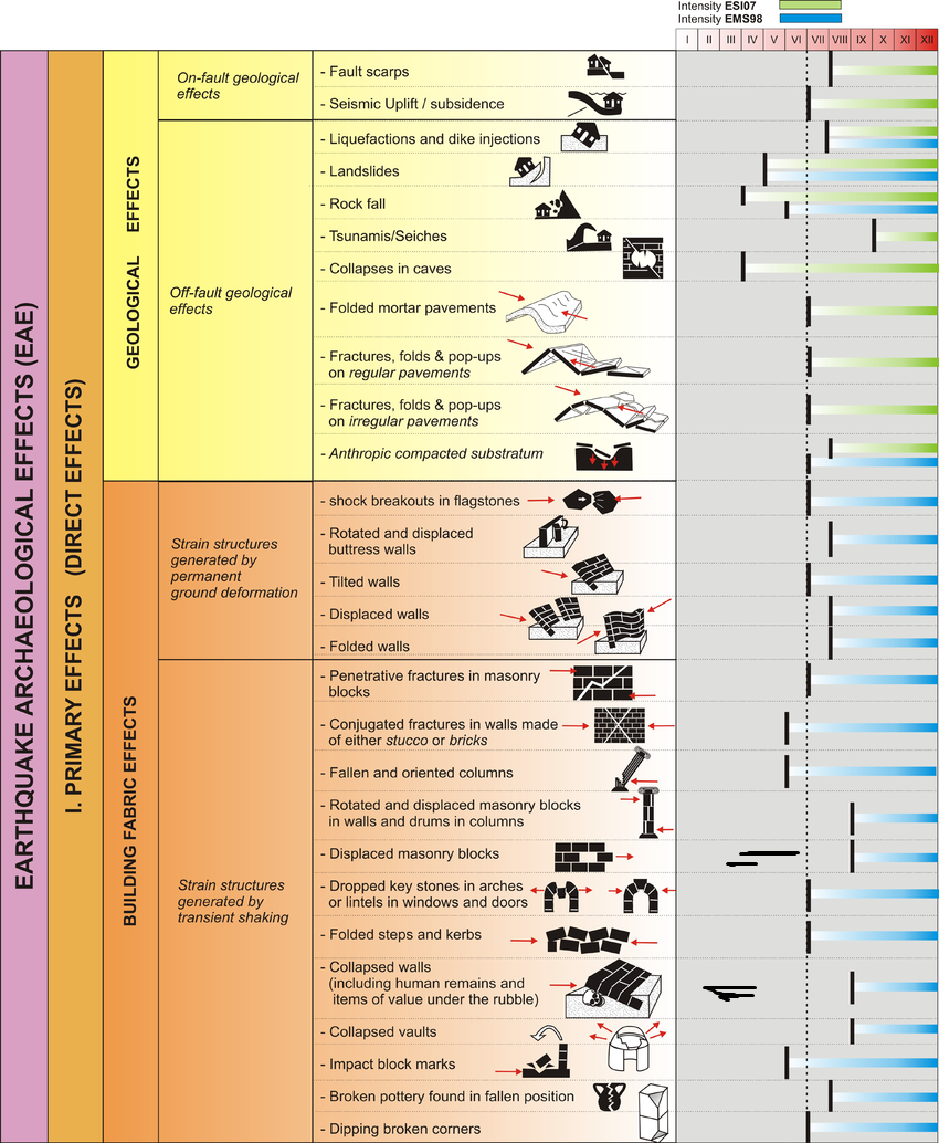
  • Environmental Effects (ESI 2007)
  • Synoptic Table of ESI 2007    Intensity Degrees from Michetti et al. (2007)
  • Environmental Effects vs. Intensity from Michetti et al. (2007)
Effect                           Location Image(s) Description Intensity           
Submarine Debris Flows Cores P12, P17, P22 and/or P29
coarse-grained anomalous deposits IV-VIII+
Estimated Minimum Intensity is VI (6).

Mass Flow Event in R/V Mediterranean Explorer cores P12, P17, P22 and/or P29 - ~12500-12000 BCE

  • Earthquake Archeological    Effects from Rodríguez-Pascua et al (2013: 221-224)
  • Environmental Effects (ESI 2007)
  • Synoptic Table of ESI 2007    Intensity Degrees from Michetti et al. (2007)
  • Environmental Effects vs. Intensity from Michetti et al. (2007)
Effect                           Location Image(s) Description Intensity           
Submarine Debris Flows Cores P12, P17, P22 and/or P29
coarse-grained anomalous deposits IV-VIII+
Estimated Minimum Intensity is VI (6).

Mass Flow Event in R/V Mediterranean Explorer cores P12, P17, P22 and/or P29 - ~5550 BCE

  • Earthquake Archeological    Effects from Rodríguez-Pascua et al (2013: 221-224)
  • Environmental Effects (ESI 2007)
  • Synoptic Table of ESI 2007    Intensity Degrees from Michetti et al. (2007)
  • Environmental Effects vs. Intensity from Michetti et al. (2007)
Effect                           Location Image(s) Description Intensity           
Submarine Debris Flows Cores P12, P17, P22 and/or P29
coarse-grained anomalous deposits IV-VIII+
Estimated Minimum Intensity is VI (6).

Event E in R/V Mediterranean Explorer core P22 - ~5466 BCE

  • Earthquake Archeological    Effects from Rodríguez-Pascua et al (2013: 221-224)
  • Environmental Effects (ESI 2007)
  • Synoptic Table of ESI 2007    Intensity Degrees from Michetti et al. (2007)
  • Environmental Effects vs. Intensity from Michetti et al. (2007)
Effect                           Location Image(s) Description Intensity           
Submarine Debris Flows Core P22
coarse-grained anomalous deposits IV-VIII+
Estimated Minimum Intensity is VI (6).

Mass Flow Event in R/V Mediterranean Explorer cores P12, P17, P22 and/or P29 - ~4350-3850 BCE

  • Earthquake Archeological    Effects from Rodríguez-Pascua et al (2013: 221-224)
  • Environmental Effects (ESI 2007)
  • Synoptic Table of ESI 2007    Intensity Degrees from Michetti et al. (2007)
  • Environmental Effects vs. Intensity from Michetti et al. (2007)
Effect                           Location Image(s) Description Intensity           
Submarine Debris Flows Cores P12, P17, P22 and/or P29
coarse-grained anomalous deposits IV-VIII+
Estimated Minimum Intensity is VI (6).

Event A in R/V Mediterranean Explorer core P22 - ~2121 BCE

  • Earthquake Archeological    Effects from Rodríguez-Pascua et al (2013: 221-224)
  • Environmental Effects (ESI 2007)
  • Synoptic Table of ESI 2007    Intensity Degrees from Michetti et al. (2007)
  • Environmental Effects vs. Intensity from Michetti et al. (2007)
Effect                           Location Image(s) Description Intensity           
Submarine Debris Flows Core P22
coarse-grained anomalous deposits IV-VIII+
Estimated Minimum Intensity is VI (6).

Mass Flow Event in R/V Mediterranean Explorer cores P12, P17, P22 and/or P29 - ~2250-2050 BCE

  • Earthquake Archeological    Effects from Rodríguez-Pascua et al (2013: 221-224)
  • Environmental Effects (ESI 2007)
  • Synoptic Table of ESI 2007    Intensity Degrees from Michetti et al. (2007)
  • Environmental Effects vs. Intensity from Michetti et al. (2007)
Effect                           Location Image(s) Description Intensity           
Submarine Debris Flows Cores P12, P17, P22 and/or P29
coarse-grained anomalous deposits IV-VIII+
Estimated Minimum Intensity is VI (6).

R/V Thuwal Core 11 Unit L Turbidite - ~1450-~1250 BCE (1σ)

  • Earthquake Archeological    Effects from Rodríguez-Pascua et al (2013: 221-224)
  • Environmental Effects (ESI 2007)
  • Synoptic Table of ESI 2007    Intensity Degrees from Michetti et al. (2007)
  • Environmental Effects vs. Intensity from Michetti et al. (2007)
Effect                           Location Image(s) Description Intensity           
Submarine Debris Flows Core 11
Event L
seismo-turbidite IV-VIII+
Estimated Minimum Intensity is VI (6).

Mass Flow Event in R/V Mediterranean Explorer cores P12, P17, P22 and/or P29 - ~1350-1150 BCE

  • Earthquake Archeological    Effects from Rodríguez-Pascua et al (2013: 221-224)
  • Environmental Effects (ESI 2007)
  • Synoptic Table of ESI 2007    Intensity Degrees from Michetti et al. (2007)
  • Environmental Effects vs. Intensity from Michetti et al. (2007)
Effect                           Location Image(s) Description Intensity           
Submarine Debris Flows Cores P12, P17, P22 and/or P29
coarse-grained anomalous deposits IV-VIII+
Estimated Minimum Intensity is VI (6).

R/V Thuwal Core 11 Unit K Turbidite - ~950-~800 BCE (1σ)

  • Earthquake Archeological    Effects from Rodríguez-Pascua et al (2013: 221-224)
  • Environmental Effects (ESI 2007)
  • Synoptic Table of ESI 2007    Intensity Degrees from Michetti et al. (2007)
  • Environmental Effects vs. Intensity from Michetti et al. (2007)
Effect                           Location Image(s) Description Intensity           
Submarine Debris Flows Core 11
Event K
seismo-turbidite IV-VIII+
Estimated Minimum Intensity is VI (6).

Mass Flow Event in R/V Mediterranean Explorer cores P12, P17, P22 and/or P29 - ~550 BCE

  • Earthquake Archeological    Effects from Rodríguez-Pascua et al (2013: 221-224)
  • Environmental Effects (ESI 2007)
  • Synoptic Table of ESI 2007    Intensity Degrees from Michetti et al. (2007)
  • Environmental Effects vs. Intensity from Michetti et al. (2007)
Effect                           Location Image(s) Description Intensity           
Submarine Debris Flows Cores P12, P17, P22 and/or P29
coarse-grained anomalous deposits IV-VIII+
Estimated Minimum Intensity is VI (6).

Event E in R/V Mediterranean Explorer core P27 - ~311 BCE

  • Earthquake Archeological    Effects from Rodríguez-Pascua et al (2013: 221-224)
  • Environmental Effects (ESI 2007)
  • Synoptic Table of ESI 2007    Intensity Degrees from Michetti et al. (2007)
  • Environmental Effects vs. Intensity from Michetti et al. (2007)
Effect                           Location Image(s) Description Intensity           
Submarine Debris Flows Core P27
Event E
Mass Transport Deposit IV-VIII+
Estimated Minimum Intensity is VI (6).

Event D in R/V Mediterranean Explorer core P27 - ~143 BCE

  • Earthquake Archeological    Effects from Rodríguez-Pascua et al (2013: 221-224)
  • Environmental Effects (ESI 2007)
  • Synoptic Table of ESI 2007    Intensity Degrees from Michetti et al. (2007)
  • Environmental Effects vs. Intensity from Michetti et al. (2007)
Effect                           Location Image(s) Description Intensity           
Submarine Debris Flows Core P27
Event D
Mass Transport Deposit IV-VIII+
Estimated Minimum Intensity is VI (6).

R/V Thuwal Core 11 Unit J Turbidite - ~450-~50 BCE (1σ)

  • Earthquake Archeological    Effects from Rodríguez-Pascua et al (2013: 221-224)
  • Environmental Effects (ESI 2007)
  • Synoptic Table of ESI 2007    Intensity Degrees from Michetti et al. (2007)
  • Environmental Effects vs. Intensity from Michetti et al. (2007)
Effect                           Location Image(s) Description Intensity           
Submarine Debris Flows Core 11
Unit J
seismo-turbidite IV-VIII+
Estimated Minimum Intensity is VI (6).

Turbidites in R/V Thuwal Cores 9, 10, and 11 in Dakar and Aragonese basins - ~300-~550 CE

  • Earthquake Archeological    Effects from Rodríguez-Pascua et al (2013: 221-224)
  • Environmental Effects (ESI 2007)
  • Synoptic Table of ESI 2007    Intensity Degrees from Michetti et al. (2007)
  • Environmental Effects vs. Intensity from Michetti et al. (2007)
Effect                           Location Image(s) Description Intensity           
Submarine Debris Flows Cores 9, 10, and 11
Core 9

Core 10

Core 11
seismo-turbidite IV-VIII+
Estimated Minimum Intensity is VI (6).

Event C in R/V Mediterranean Explorer core P27 - ~883 CE

  • Earthquake Archeological    Effects from Rodríguez-Pascua et al (2013: 221-224)
  • Environmental Effects (ESI 2007)
  • Synoptic Table of ESI 2007    Intensity Degrees from Michetti et al. (2007)
  • Environmental Effects vs. Intensity from Michetti et al. (2007)
Effect                           Location Image(s) Description Intensity           
Submarine Debris Flows Core P27
Event C
Mass Transport Deposit IV-VIII+
Estimated Minimum Intensity is VI (6).

Turbidites in all R/V Thuwal Cores except Core 11 - ~1050-~1150 CE (1σ)

  • Earthquake Archeological    Effects from Rodríguez-Pascua et al (2013: 221-224)
  • Environmental Effects (ESI 2007)
  • Synoptic Table of ESI 2007    Intensity Degrees from Michetti et al. (2007)
  • Environmental Effects vs. Intensity from Michetti et al. (2007)
Effect                           Location Image(s) Description Intensity           
Submarine Debris Flows All cores except for 11
Core 1

Core 2

Core 3

Core 4

Core 5

Core 6

Core 7

Core 8

Core 9

Core 10

Core 12

Core 13a

Core 13b

Core 14

Core 15

Core 16

Core 17

Core 18
seismo-turbidite IV-VIII+
Estimated Minimum Intensity is VI (6).

Turbidites in R/V Thuwal Cores 17 and 18 in the northern part of the Gulf - ~1200-~1300 CE (1σ)

  • Earthquake Archeological    Effects from Rodríguez-Pascua et al (2013: 221-224)
  • Environmental Effects (ESI 2007)
  • Synoptic Table of ESI 2007    Intensity Degrees from Michetti et al. (2007)
  • Environmental Effects vs. Intensity from Michetti et al. (2007)
Effect                           Location Image(s) Description Intensity           
Submarine Debris Flows Cores 17 and 18
Core 17

Core 18
seismo-turbidite IV-VIII+
Estimated Minimum Intensity is VI (6).

Event B in R/V Mediterranean Explorer core P27 - ~1292 CE

  • Earthquake Archeological    Effects from Rodríguez-Pascua et al (2013: 221-224)
  • Environmental Effects (ESI 2007)
  • Synoptic Table of ESI 2007    Intensity Degrees from Michetti et al. (2007)
  • Environmental Effects vs. Intensity from Michetti et al. (2007)
Effect                           Location Image(s) Description Intensity           
Submarine Debris Flows Core P27
Event B
Mass Transport Deposit IV-VIII+
Estimated Minimum Intensity is VI (6).

Turbidites in numerous R/V Thuwal Cores - ~1500-~1600 CE (1σ)

  • Earthquake Archeological    Effects from Rodríguez-Pascua et al (2013: 221-224)
  • Environmental Effects (ESI 2007)
  • Synoptic Table of ESI 2007    Intensity Degrees from Michetti et al. (2007)
  • Environmental Effects vs. Intensity from Michetti et al. (2007)
Effect                           Location Image(s) Description Intensity           
Submarine Debris Flows Numerous Cores
Numerous Cores
seismo-turbidite IV-VIII+
Estimated Minimum Intensity is VI (6).

Interrupted Landslide in Tiran Straits - 884-1762 CE (2σ) and ~1450-~1550 CE (1σ)

  • Earthquake Archeological    Effects from Rodríguez-Pascua et al (2013: 221-224)
  • Environmental Effects (ESI 2007)
  • Synoptic Table of ESI 2007    Intensity Degrees from Michetti et al. (2007)
  • Environmental Effects vs. Intensity from Michetti et al. (2007)
Effect          Location Image(s) Description Intensity           
Landslide Tiran Straits

landslide IV-VIII+
Estimated Minimum Intensity is VI (6).

Turbidites in R/V Thuwal Cores 2, 3, and 4 in the Tiran Deep - ~1800-~1860 CE (1σ)

  • Earthquake Archeological    Effects from Rodríguez-Pascua et al (2013: 221-224)
  • Environmental Effects (ESI 2007)
  • Synoptic Table of ESI 2007    Intensity Degrees from Michetti et al. (2007)
  • Environmental Effects vs. Intensity from Michetti et al. (2007)
Effect                           Location Image(s) Description Intensity           
Submarine Debris Flows Cores 2, 3, and 4
Core 2

Core 3

Core 4
seismo-turbidite IV-VIII+
Estimated Minimum Intensity is VI (6).

Turbidites in R/V Thuwal Cores 11, 12, 14, 15, 16, 17, and 18 in Aragonese and Eilat Deeps and possibly Core 10 in the Dakar Deep - ~1970-~2000 CE (1σ)

  • Earthquake Archeological    Effects from Rodríguez-Pascua et al (2013: 221-224)
  • Environmental Effects (ESI 2007)
  • Synoptic Table of ESI 2007    Intensity Degrees from Michetti et al. (2007)
  • Environmental Effects vs. Intensity from Michetti et al. (2007)
Effect                           Location Image(s) Description Intensity           
Submarine Debris Flows Cores 11, 12, 14, 15, 16, 17, 18, and possibly 10
Core 10

Core 11a

Core 11b

Core 12

Core 14

Core 15

Core 16

Core 17

Core 18
seismo-turbidite IV-VIII+
Estimated Minimum Intensity is VI (6).

Calculator
Convert PGA to Intensity

Variable Input Units Notes
g Peak Horizontal Ground Acceleration
Variable Output - Site Effect not considered Units Notes
unitless Conversion from PGA to Intensity using Wald et al (1999)
  

Notes and Further Reading
References

NEOM Brine Pool and Sam Purkis

Purkis, S. J., Ward, S. N., Shernisky, H., Chimienti, G., Sharifi, A., Marchese, F., Benzoni, F., Rodrigue, M., Raymo, M. E., & Abdulla, A. (2022a). Tsunamigenic Potential of an Incipient Submarine Landslide in the Tiran Straits. Geophysical Research Letters, 49(4), e2021GL097493.

Purkis, S. J., Ward, S. N., Shernisky, H., Chimienti, G., Sharifi, A., Marchese, F., Benzoni, F., Rodrigue, M., Raymo, M. E., & Abdulla, A. (2022a). Tsunamigenic Potential of an Incipient Submarine Landslide in the Tiran Straits. Geophysical Research Letters, 49(4), e2021GL097493. SUPPLEMENTARY MATERIAL

Purkis, S., Shernisky, H., Swart, P., Sharifi, A., Oehlert, A., Marchese, F., Benzoni, F., Chimienti, G., Duchâtellier, G., Klaus, J., Eberli, G., Peterson, L., Craig, A., Rodrigue, M., Titschack, J., Kolodziej, G., & Abdulla, A. (2022b). Discovery of the deep-sea NEOM Brine Pools in the Gulf of Aqaba, Red Sea. Communications Earth & Environment, 3.

Purkis, S., Shernisky, H., Swart, P., Sharifi, A., Oehlert, A., Marchese, F., Benzoni, F., Chimienti, G., Duchâtellier, G., Klaus, J., Eberli, G., Peterson, L., Craig, A., Rodrigue, M., Titschack, J., Kolodziej, G., & Abdulla, A. (2022b). Discovery of the deep-sea NEOM Brine Pools in the Gulf of Aqaba, Red Sea. Communications Earth & Environment, 3. SUPPLEMENTARY MATERIAL

Purkis, S., Rendall, B., Howes, B., & Chakraborty, M. (2026). A tectonically loaded margin: brittle slopes and two millennia of seismically triggered failure in the Gulf of Aqaba. In A. Weislogel & M. Tomlinson (Eds.), Defining the Critical Role and Impact of Sedimentology in a Sustainable Future (Vol. 26). SEPM Society for Sedimentary Geology.