Tel Rehov Trench
 Tel Rehov Trench
- Green line - Trench TR-4
- Yellow line - Subsurface trace of fault
- Red line - Seismic Line GP-5036 (to the south - bottom of image)
- Red line - Seismic Line GP-5037 (to the north - top of image)
click on image to explore this site on a new tab in Google Earth
- Location of Tel Rehov Trench in Google Earth
Tel Rehov Trench
- Green line - Trench TR-4
- Yellow line - Subsurface trace of fault
- Red line - Seismic Line GP-5036 (to the south - bottom of image)
- Red line - Seismic Line GP-5037 (to the north - top of image)
click on image to explore this site on a new tab in Google Earth - Location of Tel Rehov Trench
on govmap.gov.il
 Location of Tel Rehov Trench on govmap.gov.il
click on image to explore this site on a new tab in govmap.gov.il
Tel Rehov Trench- Green line - Trench TR-4
- Yellow line - Subsurface trace of fault
- Red line - Seismic Line GP-5036 (to the south - bottom of image)
- Red line - Seismic Line GP-5037 (to the north - top of image)
click on image to explore this site on a new tab in Google Earth
Tel Rehov Trench- Green line - Trench TR-4
- Yellow line - Subsurface trace of fault
- Red line - Seismic Line GP-5036 (to the south - bottom of image)
- Red line - Seismic Line GP-5037 (to the north - top of image)
click on image to explore this site on a new tab in Google Earth
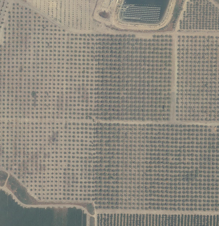
 Figure 2.7a
The surface scarp system and subsurface trace of the underlying marginal fault of the DSR (dashed line), as detected in geophysical surveys by Gardosh and Bruner 1998 and Bruner, Zilberman and Amit 2002. The traces of seismic lines GP-5036 and GP-5037 are marked on the aerial photo.
Mazar et. al. (2020 v.1)

Figure 7
Seismic Line GP-5036. Note the lack of seismic reflectors on the eastern side of the main fault.
Zilberman et al (2004)

Figure 20
Fig. 20 Reconstruction of the main tectonic events in the fault exposed in Trench TR-1.
- Deposition of the upper part of the tufa sequence (20-30 ka)
- Displacement of the sequence accompanied by truncation of the upper block (between 20-30 ka and 2700 Y.B.P.)
- Displacement of about 1.5 m (around 2700 years before present
- Deposit of colluvium (Colluvium 1)
- Development of incipient soil during a short stable period
- Displacement of about 1.5 m (around 2600 years before present)
- Deposit of colluvium (Colluvium 2)
- Deposition f the Upper Unit. Fracturing of the entire sequence.
Zilberman et al (2004)
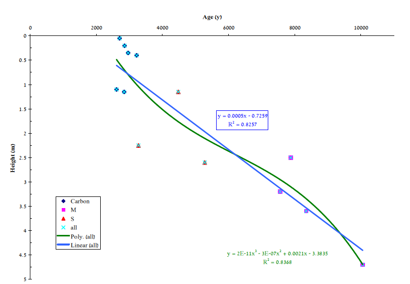 Figure 19
The ages received from radiocarbon dating, presented against their position in the sequence
click on image to open in a new tab
Zilberman et al. (2004)
The Bet She'an Valley is the easternmost part of a NW-SE-oriented system of extensional Miocene depressions that include the Harod and Yizre'el (Esdralon) valleys (Schulman, 1962; Horowitz, 1979; Shaliv, 1991) (Fig. 1). It is bounded to the east by a morphotectonic scarp 20-40 m high that marks the trace of the western marginal fault of the Dead Sea Rift (DSR) (Gardosh and Bruner, 1998; Bruner et al., 2002). The Bet She'an depression is apparently older than the DSR. It is part of a regional NW-SE extensional tectonic system termed "The Erithrean System" (Shalem, 1954; Horowitz, 1979), that exhibits the same orientation as the Red Sea and the Gulf of Suez. Matmon (2000) suggested that the uplifted Carmel block, the Bet She'an and the Yizre'el valleys, and the Lower Galilee tilted blocks, are all part of a NW-SE-oriented fossil Neogene rift.
 Figure 1
Location map showing the main tectonic elements
click on image to open in a new tab
Zilberman et al. (2004)
The DSR formed as an elongated, deep, intercontinental basin in the Late Miocene or early Pliocene (Picard, 1951; Garfunkel, 1981, 1988) due to a change in plate motion (Garfunkel, 1981). However, the Dead Sea Fault (DSF) has been active at least since the break-up of the African plate in the Early Miocene (Garfunkel, 1981). During the Miocene, it was characterized by "pure strike slip" (Garfunkel, 1981) associated with development of deep sedimentary basins between left-step segments. One of these basins occupied the present northern Jordan Valley (Biqa't Kinnarot), where a thick (<4 km) Neogene sequence was penetrated by the Zemah drill hole (Marcus and Slager, 1985)
The Bet She'an area is underlain by a thick Neogene to Quaternary continental sequence of the Tiberias (Teverya) and Dead Sea groups (Shaliv, 1991; Shaliv et al., 1992). An older Late Cretaceous to Eocene marine sequence is exposed in the uplifted Mount Gilboa' block, which rises above the Bet She'an Valley to the southwest (Fig. 2). The Neogene sequence is exposed along the foot of Mount Gilboa'. The Pleistocene units exposed in the Bet She'an area are: Early to Middle Pleistocene Wadi Malih Conglomerate, the tufa sequence of the Bet She'an Formation, and redeposited red soils of the Faza'el Member of the Lisan Formation. The Late Pleistocene Lisan Formation is exposed further to the east in the Jordan Valley.
 Figure 2
Geologic map of Bet She'an area (Geology from Sneh et al., 1998)
click on image to open in a new tab
Zilberman et al. (2004)
2.1 The Wadi Malih Conglomerate (Schulman and Rosenthal, 1968)
A unit of coarse conglomerate cemented by carbonate, about 40 m thick, is exposed along the Nahal Bezeq channel and is assumed to underlie recent alluvium along the eastern mountain front of the uplifted Gilboa' block (Rosenthal, 1965). The conglomerate is composed of clasts derived from all the rock units exposed in the eastern Samaria area, including those of Early Cretaceous age (Hatzor, 1991). It is dominated by clasts originating from Eocene limestone, Senonian chalk and Miocene basalt units. The morphology of this unit suggests that it was deposited in a series of alluvial fans along the eastern front of Mount Gilboa'. Most of the exposed conglomerate was deposited in the ancient, abandoned alluvial fan of Nahal Bezeq. At present, the stream-channel of Nahal Bezeq is confined to a narrow valley, deeply incised in its ancient alluvial fan.
The upper part of the alluvial fan of Nahal Bezeq is cemented by carbonate, probably of pedogenic origin (calcrete). It is covered by red soil, which was apparently eroded from the mountainous terrain to the west. The age of the Wadi Malih Conglomerate is not entirely clear, but it is assumed to be of Late Pliocene to Early Pleistocene age (Schulman and Rosenthal, 1968; Bartov et al., 1981) or Early to Middle Pleistocene (Hatzor, 1988).
The Wadi Malih Conglomerate is overlain in the east by limnic-lacustrine sediments of unknown age. Both units are tilted and unconformably overlain by the Lisan Formation (Schulman and Rosenthal, 1968).
2.2 The Lisan Formation
The Wadi Malih Conglomerate is unconformably overlain by the lacustrine Lisan Formation (Rosenthal, 1965). The Lisan Formation is exposed mainly along the erosion escarpment that separates the present stream valley of the Jordan River (the "Zor") from the morphological surface of the Lake Lisan floor (the "Or"). The highest elevation of the Lisan Formation in the Biqa't Kinnarot Valley is 170 m b.s.l. (Hazan et al., 2001) and it is up to 25 m thick. It is mostly clastic with a few aragonite laminae (Heimann and Braun, 2000) and contains three diatomite beds (Begin et al., 1974). East of Bet She'an, the bedded lacustrine sequence of the Lisan Formation forms a flat surface, 1-3 km wide at an altitude of -240.5 m. The age of the Lisan Formation in the Kinnarot basin ranges between 27 ka and 23 ka, when Lake Lisan attained its highest level (Begin et al., 1974; 1980; Braun, 1992) and flooded the Kinnarot basin (Hazan et al., 2001). A drop in the lake level below the morphological barrier near Wadi Malih, probably at an altitude of -250 m, differentiated Lake Lisan into southern and northern water bodies, exhibiting separate fluvial histories (Begin et al., 1974; Neev, 1976; Hazan et al., 2001).
2.3 The Bet She'an Formation (Horowitz, 1979)
This unit consists of tufa sediments that are widespread west of the escarpment of the marginal fault of the DSR. They build a flat surface extending from Sede Terumot in the south to the margin of the eastern Galilee, north of Bet She'an. A 20-40 m thick tufa sequence is exposed along the scarp of the Bet She'an fault, although boreholes penetrated a sequence more than 60 m thick. West of the escarpment, the tufa is mostly covered by a thin (1-5 m) layer of mainly fluvial sediments and soils. The western boundary of the tufa terrace is not exposed, but it is assumed to extend up to the alluvial fan belt along the foot of the uplifted Gilboa' block.
The tufa sequence is sub-horizontally bedded (Fig. 3) and consists mainly of phytoclast tufa interbedded with intraclast tufa and stromatolitic tufa, characterizing low-energy, braided fluviatile environments (Pedley, 1990). Horowitz (1979) correlated this tufa with the Faza'el Member of the Lisan Formation and attributed to it a Late Pleistocene to Holocene age. Rosenthal (1980) suggested that the deposition of this unit was synchronous with the last stage of Lake Lisan or slightly postdated its desiccation.
The upper 18 m of the tufa sequence was dated in a quarry near Rehov by Kronfeld et al. (1988) using 14C and U/Th methods. The age of the lower part was ~41 ka and the upper part ~22 ka, supporting the idea that this tufa was laid down during the Lake Lisan period. The source of the water that deposited the tufa seems to be related to the fault belt, which was detected by a geophysical survey along the eastern foot of Mount Gilboa' by Gardosh and Bruner (1998).
2.4 The Faza'el Member of the Lisan Formation (Horowitz, 1974)
The Lisan Formation is overlain by fluvio-lacustrine sediments of the "unnamed clastic unit" (Begin et al., 1974), termed - Faza'el Member of the Lisan Formation by Horowitz (1974, 1979). In the central Jordan Valley, between Jericho and Wadi Malih, this unit has a typical reddish color and consists of gravel, silt and clayey reddish loam, bearing lacustrine sediments with freshwater gastropods (Begin et al., 1974; Bar-Yosef et al., 1974). Near the western mountain front of the DSR, it fills the valleys of the major streams which are incised in the Lisan sediments, and further to the east it was also deposited on top of the Lisan Formation. Abundant Epi-Paleolithic, Neolithic and Natufian artifacts are embedded in this unit near Faza'el (Bar-Yosef et al., 1974; Schuldenrein and Goldberg, 1981).
This unit seems to reflect intensive erosion of red soils, probably terra rossa, from the Samaria hills and the western slopes of the Trans-Jordan Plateau. Begin et al. (1974) suggested that it was deposited in a climate drier than that characterizing the Lisan period, but wetter than the present one. However, the intensive erosion of soils from the highlands around the rift might suggest both a decline of vegetation cover probably due to decrease in the amount of precipitation, or an increase in the rain shower intensity, resulting in intensive floods and rapid erosion. The lacustrine facies seems to represent fresh local water bodies rather than a continuous lake, as in the Lisan period.
A similar unit was described from the northern Jordan Valley by Neev (1976), where it covers Chalcolithic and Early Bronze sites. Its upper part contains freshwater gastropods that yielded a 14C age of 5400 ± 180 YBP (Neev, 1976). Therefore, this unit seems to be younger than the Faza'el Member in other areas, although it occupies the same stratigraphic position, i.e., above the Lisan Formation.
According to Neev (1976), this unit was deposited on the exposed bottom of Lake Lisan after its recession, and it predated the entrenchment of the Jordan River. This view was supported by Koucky and Smith (1986) who reconstructed an extensive swamp in the northern Jordan Valley in the 6th millennium BP.
A red silty unit originating from redeposited soils covers the alluvial fan of Nahal Bezeq and builds the upper sequence in some areas of the Jordan Valley. In the Nahal Harod Valley east of Bet She'an, well-bedded red beds overlie lacustrine marl of the Lisan Formation. The age of this unit in the study area is not entirely clear and it seems that in the valley margins it was first deposited during the Late Pleistocene and at its center, after the recession of Lake Lisan.
The morphology of the Bet She'an area reflects three tectonic blocks (Fig. 4):
 Figure 4
A cartoon illustrating the regional structure and morphology of the Bet She'an area
click on image to open in a new tab
Zilberman et al. (2004)
- The upper block is Mount Gilboa', which rises above the Bet She'an Valley in the southwest. This block is tilted to the southwest and is bounded in the northeast by a belt of normal faults that form a series of northeastward descending blocks (Hatzor 1991; Gardosh and Bruner, 1998).
- The Middle Block (Bet She'an Valley) is bounded by Mount Gilboa' in the west and the western marginal fault of the DSR in the east. The trace of the marginal fault is associated with a N-S oriented morphostructural step 20-40 m high (Fig. 5) that separates between the Bet She'an and the Jordan valleys (Zilberman et al., 2002; Bruner et al., 2002). The Bet She'an Valley is underlain by a Neogene to Recent continental sequence estimated to be 500-900 m thick (Gardosh and Bruner, 1998).
- The eastern, lower block (Jordan Valley) extends east of the western marginal fault of the DSR. It is underlain by a very thick continental sequence, the base of which is too deep to be detected by the seismic line (Gardosh and Bruner, 1998).
 Figure 5
The morphological scarp east of Bet She'an
click on image to open in a new tab
Zilberman et al. (2004)
3.1 The escarpment along the Dead Sea Rift western marginal fault
The western marginal fault of the Dead Sea Rift was detected in the subsurface between Bet She'an and Sede Eliyyahu by a deep seismic reflection survey (Gardosh and Bruner, 1998, Fig. 6). On the surface it is manifested as a series of morphological escarpments, each seeming to represent a branch of the deep fault. The southern scarp (termed here: "Rehov fault") extends from the Sede Terumot settlement in the south to Tel Rehov in the north (Fig. 6). It forms a 15-20 m high scarp which separates between a high tufa plateau in the west and a low plain covered by soil in the east.
 Figure 6
The surface scarp system and the subsurface trace of the marginal fault of the DSR as detected in geophysical surveys by Gardosh and Bruner, 1998 and Bruner et al., 2002 (deliniated in yellow). The traces of seismic lines GP-5036 and GP-5037 are marked on the air photo
click on image to open in a new tab
Zilberman et al. (2004)
The northern escarpment (termed here: "Bet She'an fault") begins near the northeastern part of Tel Rehov and extends northward to the northern Jordan Valley. North of Kibbutz 'En haNaziv the escarpment is 25-40 m high (Fig. 5), separating between a high tufa plateau in the west and a low land covered by soil in the east. East of Bet She'an it splits into two branches: one continues northward toward the Sea of Galilee, and the second runs to the northwest toward Tel Bet She'an and seems to merge with the N-S oriented fault system that separates between the tilted blocks of the lower Galilee and the Jordan Valley. A branch of the northward-trending fault is probably exposed in the northern wall of the Nahal Harod creek (coord. 19925/21250) at the foot of a morphological scarp. Here, it is expressed as a vertical fracture that separates between a scarp covered by coarse basalt colluvium coated by tufa in the west, and bedded tufa in the east.
3.2 Geophysical data (after Bruner et al, 2002)
Two E-W oriented high-resolution, seismic-reflection lines were shot across the escarpment that separates between the Bet She'an Valley (the middle block) and the Jordan Valley (the eastern block) (Fig. 6). (For technical details see Bruner et al., 2002) The southern line (GP-5036), which is 1800 m long, is located north of Tel Rehov. It starts on the high tufa plateau in the west, crosses a 60 m high gentle slope and continues some 500 m on the eastern lower block. The northern line (GP-5037) is located some 800 m north of the deep seismic line made by Gardosh and Bruner (1988). It is about 700 m long and crosses a steep scarp 40-50 m high, located just east of the eastern outskirts of Bet She'an.
Figure 7
Seismic Line GP-5036. Note the lack of seismic reflectors on the eastern side of the main fault.
click on image to open in a new tab
Zilberman et al. (2004)
Line GP-5036 (Fig. 7) shows clear reflectors west of the main fault, which is crossed by the line at the base of the gentle slope (at station 280). To the east of the main fault there are no clear reflectors except at the upper part of the sequence. The main fault splits at a depth of 0.5 sec to several low angle branches that form a shear zone, some 400 m wide between stations 280 and 200. Another fault, which is not connected directly to the main fault, underlies trench TR1, which was excavated at the middle part of the slope. All these faults seem to displace the surface, and some of them are expressed as N-NW oriented low steps or undulations in the cultivated area.
 Figure 8
Seismic Line GP-5037.
click on image to open in a new tab
Zilberman et al. (2004)
The sequence, which underlies line GP-5037 (Fig. 8), shows clear reflectors only in restricted parts of the upper section, and therefore, its interpretation is problematic. A shallow, lens-shaped body, characterized by irregular reflectors, which extends in the upper part of the sequence between stations 100 and 40, might represent a tufa sequence.
Four normal faults were detected along this line: the two western faults, located under the high block, were interpreted as part of the main marginal fault. This interpretation is also based on the results of the nearby seismic line made in 1998 by Gardosh and Bruner. The steep scarp is also underlain by a fault and another fault is located under the distal lower part of the slope.
4.1 The drainage networks
The present drainage system of the Bet She'an valley is mainly artificial and the previous natural stream network was eliminated during the last 50 years by intensive cultivation. However, the natural drainage network is still clearly visible on air photos taken in 1945 by the British authorities (PS), and it also appears on a 1:50.000 scale topographic map published in the same year. This system exhibits a complex pattern of abandoned and active channels (Fig. 9) with opposite flow directions.
 Figure 9
The ancient drainage systems on both sides of the marginal fault, marked on air-photos from 1945. The western system was still active when the photos were taken.
click on image to open in a new tab
Zilberman et al. (2004)
The area between the eastern slopes of Mount Gilboa' and the Jordan River is divided by the escarpment of the marginal fault into two drainage networks: the western network drains the eastern slopes of Mount Gilboa' and the Middle Block to Nahal Harod in the north. The streams do not cross the marginal fault escarpment eastward, but drain to a marsh that was located on the elevated block, just west of the escarpment. This marsh was drained northward toward Nahal Harod. An anomalous drainage system pattern is also observed in the Jordan Valley east of the escarpment. This area gently descends (gradient of 1%-2%) to the east, and is separated from the present floodplain of the Jordan River by a series of erosion escarpments 30-50 m high.
Two drainage systems can be distinguished on this block. Active, east-flowing perennial streams and an abandoned network that shows a westward-converging channel pattern. The active streams are fed by springs that are scattered along the trace of the marginal fault escarpment, each forming a small, steep-wall valley cut into the slope of the escarpment. Several hundred meters eastward, the stream-channels turn to the south or north, and flow along the escarpment. Some of the streams have no clear channel in this area. A few of the perennial streams flow eastward all the way to the Jordan River in relatively straight channels.
The abandoned channel-network starts near the western margins of the Jordan River valley and can be traced westward up to a distance of several hundred meters from the marginal fault escarpment. Some of these channels are occupied today by east flowing streams, or by artificial canals. Near the escarpment, where this network meets the east flowing springs, the channels lose their morphological identity or turn northward or southward.
4.2 Interpretation
The escarpment system that separates between the Bet She'an and the Jordan valleys forms a barrier to the east-flowing streams that drain Mount Gilboa'. This situation is attributed to a westward tilting of the Bet She'an Valley along the western marginal fault of the DSR. The westward tilting post-dated the tufa sequence, which was deposited in eastward-flowing streams. Therefore, the tilting is related to the young tectonic phase, which also formed the present escarpment along the fault-trace.
The situation on the eastern, down-faulted block (Jordan Valley) is much more complicated. The present eastward gradient of this area is well manifested by the flow direction of the main springs and Nahal Harod. However, the geometry of the abandoned-stream network indicates that a previous westward-flowing channel system drained this area in the past. Therefore, it seems that the post-tufa tectonic activity along the marginal fault also caused a westward tilting of the eastern, down-faulted block.
The westward-flowing drainage system is probably young, not older than mid-Holocene. This conclusion is based on observations by Neev (1976) that Chalcolithic sites in the Jordan Valley are still covered by lacustrine sediments, a view which is also supported by Koucky and Smith (1986). It is not clear when the westward gradient of the Jordan Valley was inverted to the present eastward gradient. However, it must be very young, reflecting both tectonic activity and the incision of the Jordan River in the Jordan Valley. The preservation of the abandoned channel system in spite of the continuous intensive cultivation of this area, also support the young age of the inversion.
Figure 6
The surface scarp system and the subsurface trace of the marginal fault of the DSR as detected in geophysical surveys by Gardosh and Bruner, 1998 and Bruner et al., 2002 (deliniated in yellow). The traces of seismic lines GP-5036 and GP-5037 are marked on the air photo
click on image to open in a new tab
Zilberman et al. (2004)
The mound of Tel Rehov is located in a tectonic depression that developed between two segments of the marginal fault of the DSR: Rehov and the Bet She'an (Fig. 6). It was built on an eastward tilted elevated tufa block, which is bounded by faults in the south, north, and west (Zilberman et al., 2002).
 Figure 10
A subsurface map of the tufa block which underlies Tel Rehov. The faults are reconstructed from the seismic survey (for more information see Zilberman et al., 2002)
click on image to open in a new tab
Zilberman et al. (2004)
Tel Rehov is composed of two mounds that are separated by a steep step (Fig. 10). The height of the southern mound is 20-25 m above its surroundings, whereas the northern low mound is 8-10 m high (Fig. 12). The base of the step that separates between the two parts of the Tel is drained eastward by a channel, which together with the base of the escarpment forms a morphologic lineament. This step is underlain by a fault, which was detected in the tufa under the anthropogenic sequence by a seismic reflection survey (Zilberman et al., 2002).
 Figure 12
A detailed map of Tel Rehov (from Mazar, 1999). The seismic lines are marked on the map.
click on image to open in a new tab
Zilberman et al. (2004)
An archaeological excavation is being carried out in the lower part of the Tel since 1997 by Prof. A. Mazar from the Hebrew University revealed continuous occupation between the Late Bronze Age (13th century B.C.E.) and the Iron age II (10th/9th centuries B.C.E.) (Fig. 13). The upper mound was established probably in the 20th century B.C.E. The final destruction and abandonment of the city is attributed by Mazar (1999) to the Assyrian conquest of 732-734 B.C.E.
 Figure 13
The archeological sequence of the lower mound. The white line marked the top of the underlying tufa.
click on image to open in a new tab
Zilberman et al. (2004)
At the southeastern part of the lower mound, excavations exposed structures from the 9th century that are tilted slightly to the south towards the lineament that separates the two parts of the Tel (Fig. 14). This tilt was attributed by Mazar (1999) to young tectonic activity.
 Figure 14
The tilted part of the lower mound. A northward view from the upper mound. The dotted line runs along the boundary between the two parts of the tel.
click on image to open in a new tab
Zilberman et al. (2004)
Sediments deposited in a shallow marsh capped by a 2 m thick tufa unit (dated between the 16th and 13th centuries B.C.E.) underlie the lower mound (Fig. 13). This sequence is elevated at present above the base level east of the Tel (east of the marginal fault) and, therefore, might represent a young tectonic uplift of the Tel area.
The aim of the paleoseismic study was to gain more information about seismic events related to young tectonic activity along the western marginal fault of the DSR. Three trenches were excavated along the scarp, two located above subsurface faults detected in a high resolution seismic reflection survey. A fault was found only in trench TR1.
7.1 The site of Tel Rehov trench (TR-1)
Trench TR1 is located north of Tel Rehov across the southern part of the Bet She'an fault. In this area, a gentle slope, 40-50 m high, separates the tufa plateau in the west from a lower surface capped by soil in the east (Fig. 15). The site of the trench is located where a steep escarpment is visible in air photos taken by the British authorities in 1945. The morphological expression of this fault can be traced northward to Kibbutz 'En haNaziv where it forms a clear step. Several springs are located along the trace of the fault: En Neshev, some 200 m north of the trench and En Naftali and En Yehuda, in Kibbutz 'En haNaziv. North of 'En haNaziv, the steps of the fault merge with the 40 m high escarpment that runs northward toward Bet She'an.
The subsurface fault exposed in the trench was detected by a short (500 m), shallow, high resolution seismic reflection line, shot across the escarpment and a 1800 long, deep, high resolution seismic reflection line, which was shot across the entire morphological step (Bruner et al., 2002). The main stem of the marginal fault was detected some 500 m east of the trench site, exhibiting a dip of 70° eastward (Fig. 7). A low angle (30-40°) array of listric faults splits from the main fault to the west, forming a fault belt that extends up to 100 m east of the trench. The fault crossed by the trench is visible up to a depth of 0.5 sec (TWT), near the top of the Miocene Hordos Formation.
7.2 The stratigraphic units in trench TR-1
 Figure 16
The scarp of the fault exposed in the trench. The line seperates between the tufa and the overlying sediments.
click on image to open in a new tab
Zilberman et al. (2004)
 Figure 17
Fractures crossing the young sequence
click on image to open in a new tab
Zilberman et al. (2004)
The trench exposed a scarp about 3 m high (Fig. 16), built of tufa. It is overlain by a silty gray-brown sequence consisting mainly of reworked soils and tufa fragments, which contain pieces of pottery (Figs. 17, 18).
 Figure 18
The log of Trench TR-1
click on image to open in a new tab
Zilberman et al. (2004)
7.2.1 The tufa unit
This unit is composed of homogeneous, yellowish, soft chalky tufa (Figs. 16, 17). It consists of small (2-5 mm), angular and rounded tufa clasts, embedded in calcareous silt. A crude sub-horizontal layering is noted among the tufa clasts. The upper part of the tufa in the uplifted block contains allochthonous coarse fragments (20-30 cm) derived from phytotherm tufa. A few of these are embedded in the chalky tufa, but most are scattered on the eroded surface at the top of the tufa. The ages of the tufa are 645 ka in the upper block, and 322.5 ka in the lower block (determined by U/Th method).
The top of the tufa of the upper block is eroded and marked by a microrelief of 20-30 cm. It is covered by hard angular tufa fragments, some derived from nearby phytotherm tufa and some from hardpan (calcrete?), which developed on an exposed tufa surface. The fragments are embedded in a gray matrix of silt and clay, which compose the overlying sediment. The size of the fragments decreases upward to a few cm. The thickness of this weathering mantle is up to 40 cm.
The top of the tufa in the lower block does not contain fragments of phytotherm tufa and the contact with the overlying sediment is smooth and fresh. It is covered with a thin unit (up to 15 cm) of tufa clasts (0.5-2 cm), mostly rounded, in a white-yellowish calcareous silt matrix. In some places, very shallow channels filled by oncolites (1-2 cm) can be observed. The most developed channel, which is 10-30 cm deep and 40-50 cm wide, is found at the foot of the scarp. This unit passes upward to brown-gray silt with some clay, which is covered by unit 1.
7.2.2 Colluvial unit 1
This consists of angular tufa fragments (up to 10 cm), embedded in a brown-gray silty matrix. It also contains small (1-2 cm) rounded oncolites, mostly weathered, pieces of pottery, charcoal fragments, and landsnails. The size of the tufa fragments decreases eastward down to 2-3 cm near datum 14. From datum 14 eastward, only a few tufa fragments are found in the silty matrix. The fragments derived mainly from hard tufa and are similar to those that cover the upper block. A dark calcic paleosol that appears near the outlet of the trench seems to correlate with this unit. The top of the unit is characterized by incipient soil, which contains rhizolithes and a primary soil-profile.
Three charcoal samples collected from this unit (for location see Fig. 18) yielded ages ranging between 2706 ± 49 BP (TR1.10) at the base to 2856 ± 48 (TR1.12) and 2963 ± 96 BP (TR 1.7) at the top. A radiocarbon age of 2843 ± 66 (TR. 1.11) was determined for the upper edge of the colluvial unit near the scarp. It is suggested that this inverse stratigraphy (Fig. 19) reflects the trend of erosion of the hillslopes above the scarp. The first to be eroded was the uppermost sediment, which naturally was the younger and contains the most recent charcoal. This young sediment was the first to be deposited on the downfaulted block. The older parts of the sequence of the hill were next to be exposed and eroded and, thus, formed the upper part of unit 1. Based on the above erosion scenario, we conclude that the age of this unit is represented by the youngest charcoal age, around the 7th century B.C.E.
Figure 19
The ages received from radiocarbon dating, presented against their position in the sequence
click on image to open in a new tab
Zilberman et al. (2004)
7.2.3 Colluvial unit 2
The transition from unit 1 to unit 2 is gradual. Unit 2 contains scattered tufa fragments, a few centimeters in size, floating in a gray silty matrix. The tufa fragments are similar to those of unit 1, their size decreasing from the scarp eastward and their amount decreasing both upward in the sequence and eastward. The unit also contains rounded oncolites, pottery pieces, freshwater gastropods (melanopsis) and landsnails. On the lower block it is about 1.5 m thick while on the upper block it is reduced to 20-40 cm. Unit 2 passes gradually to the overlying unit 3.
The upper part of the scarp, covered by unit 2 is eroded, indicating a slow deposition of unit 2 on the downfaulted block. The low deposition rate is also manifested by the lack of any sedimentary structure in unit 2, probably due to intensive bioturbation and continuous cultivation. Seven samples were dated in this unit using the radiocarbon method: two charcoal, two land snails and three melanopsis shells (for location see Fig. 17). A charcoal sample collected from the lower part of the sequence yielded an age of 3222 ± 54 Y.B.P. (TR 1.13). Another charcoal sample from the middle part of the unit yielded an age of 2614 ± 47 Y.B.P. (TR 1.17). A nearby land snail sample yielded an age of 4482 ± 51 Y.B.P. (TR 1.16a). Three melanopsis samples collected from the upper part of the unit were dated at 7882 ± 53 Y.B.P. (TR 1.9), 7560 ± 52 Y.B.P. (TR 1.4), and 8350 ± 51 Y.B.P. (TR 1.3). A land snail sample collected from the upper part yielded an age of 3277 ± 49 Y.B.P. (TR 1.14).
The radiocarbon ages in unit 2 show the same inverse pattern as that in unit 1 (Figs. 17, 18), presumably resulting from a similar process of differential erosion of the hillslopes above the uplifted block. However, some of the samples are older than those found in unit 1, indicating that the ongoing erosion of the upper block exposed older units to weathering processes. The melanopsis shells at the top of the unit yielded the oldest age, reflecting a remote source of water-laid sediment, probably some type of tufa. The youngest radiocarbon age in this unit is younger by 100 years than the age of unit 1, supporting the pedological data that suggests a short break between the depositions of the two colluvial units.
7.2.4 The upper gray unit (Unit 3)
Unit 3 was deposited on both the lower and the upper blocks, forming a continuous cover on the previous tectonic relief. It is homogeneous, without any sedimentary structure, and consists of gray silt with some clay. It contains scattered oncolites but no hard, angular tufa fragments such as those found in the lower units. It also contains fresh melanopsis shells, sometimes with the original pinkish color, and pieces of pottery. A few thin, sub-horizontal lenses (2-5 cm thick and 20-100 cm long) of small (1-3 cm) well-rounded and well-sorted oncolites are scattered in the lower part of this unit.
A sample of land snail collected from the contact between units 2 and 3 yielded an age of 5282 ± 89 YBP (TR 1.18), and a melanopsis shell sample from the upper part yielded an age of 1005 ± 56 (TR 1.1).
The inverse stratigraphy manifests the ongoing erosion of the upper block and the continuous removal of the upper young sequence resulting in the exposure of the lower and older units to weathering. It is assumed that the source of the fresh melanopsis shells are historical irrigation canals that criss-crossed the cultivated area.
7.2.5 The upper soil
The slope is covered with a gray O-horizon, 20-40 cm thick. There is no clear soil profile, probably as a result of continuous bioturbation and cultivation of this area.
7.3 The fault
The escarpment of the fault in the tufa units is highly weathered as a result of the low resistivity of the soft tufa to erosion processes. There is no clear fault plane and the low gradient of the upper part of the escarpment suggests rapid slope degradation. However, two sets of vertical fractures can be distinguished in the soft tufa: one at the base of the scarp and a second two meters to the east. From each fracture zone there is one fracture that can be traced up to the lower part of unit 3 (Figs. 17, 18). No offset was detected along these two fractures.
7.4 Interpretation
The fault exposed in trench TR-1 is only one branch of the wide fault belt associated with the western marginal fault of the DSR. The total vertical displacement along this fault zone is manifested by the separation between the upper tufa surface west of the fault (altitude ~ -120 m.) and the lower surface east of the fault (altitude ~ -180 m), i.e., at least 50-60 m. It is assumed that this displacement post-dated the deposition of the tufa, e.g., post-20 ka according to Kronfeld et al. (1988) or post 30 ka according to the age of the tufa exposed in the trench. Therefore, the displacement manifested by the fault exposed in the trench reflects only a small portion of the total displacement along the marginal fault belt.
7.4.1 The pre-alluvial-colluvial sequence faulting events
The ~30 ky difference between the ages of the tufa units on both sides of the fault in the trench reflect a long period of tectonic activity that predated the three tectonic events detected in the colluvial sequence. This tectonic activity was associated with an unknown number of vertical displacements. The age difference between the upper and the lower blocks suggests that a sequence of tufa that was deposited between 60 and 30 ka was removed by erosion from the uplifted block before the formation of the present escarpment (Fig. 20a-c).
Figure 20
Reconstruction of the main tectonic events in the fault exposed in Trench TR-1.
- Deposition of the upper part of the tufa sequence (20-30 ka)
- Displacement of the sequence accompanied by truncation of the upper block (between 20-30 ka and 2700 Y.B.P.)
- Displacement of about 1.5 m (around 2700 years before present
- Deposit of colluvium (Colluvium 1)
- Development of incipient soil during a short stable period
- Displacement of about 1.5 m (around 2600 years before present)
- Deposit of colluvium (Colluvium 2)
- Deposition f the Upper Unit. Fracturing of the entire sequence.
click on image to open in a new tab
Zilberman et al. (2004)
The amount of the total displacement cannot be reconstructed at present since the thickness of the post 64 ka tufa sequence eroded from the upper block is not known. However, in the quarry dated by Kronfeld et al. (1988), 2 km north of the trench, 18 m of tufa were deposited during a period of 20 ky (between 40 ka and 20 ka), indicating an average deposition rate of 1 m/1000 years. Since the upper part of the tufa forms a continuous flat surface all the way from the quarry to the trench site, and the stratigraphy is sub-horizontal, it might be argued that a correlation can be made between the two sites. Therefore, it is estimated that the eroded sequence was some 30-40 m thick and this is also the minimum total displacement.
Each seismic event was followed by an erosion period, which removed the tufa sequence from the uplifted block. However, the sharp contact between the tufa and the colluvium of the lower block, which shows no evidence of weathering, suggests that this block was also exposed to erosion. Assuming that the age of the upper part of the sequence in the trench is the same as in the Rehov quarry (about 20 ka), the thickness of the tufa eroded from the lower block is estimated to be some 10 m. The shallow channels filled by tufa oncolites found on the top of this block, suggest that at least part of this erosion can be related to fluvial environments.
The number of seismic events represented by the vertical offset along the branch exposed in the trench (about 30 m) is dependent on the estimated offset allocated to each event. If for example, we assume an average offset of 1 m per event, then 30 earthquakes with average magnitudes of M 6.5 and recurrence intervals of 1000 y can be reconstructed for the last 30 ky.
7.4.2 Faulting event I
Figure 20
Reconstruction of the main tectonic events in the fault exposed in Trench TR-1.
- Deposition of the upper part of the tufa sequence (20-30 ka)
- Displacement of the sequence accompanied by truncation of the upper block (between 20-30 ka and 2700 Y.B.P.)
- Displacement of about 1.5 m (around 2700 years before present
- Deposit of colluvium (Colluvium 1)
- Development of incipient soil during a short stable period
- Displacement of about 1.5 m (around 2600 years before present)
- Deposit of colluvium (Colluvium 2)
- Deposition f the Upper Unit. Fracturing of the entire sequence.
click on image to open in a new tab
Zilberman et al. (2004)
The first event is represented by unit 1, which was deposited above the downfaulted block and the newly formed fault scarp (Fig. 20d). The minimum vertical displacement, represented by the height of the colluvial unit is 1.2 m. This seismic event occurred in the 7th century B.C.E. The formation of the escarpment was followed by erosion of the upper slope of the hill above the escarpment and deposition of colluvium, which contains coarse tufa fragments. It also contains reworked sediments originated from 3 ky old units exposed by erosion on the upper block. An undeveloped profile at the top of this unit indicates that it was stabilized for a short period before the deposition of unit 2 (Fig. 20e). The minimum magnitude of this earthquake, deduced from the vertical displacement is M 6.5-6.6 (Wells and Coppersmith, 1994).
7.4.3 Faulting event II
Figure 20
Reconstruction of the main tectonic events in the fault exposed in Trench TR-1.
- Deposition of the upper part of the tufa sequence (20-30 ka)
- Displacement of the sequence accompanied by truncation of the upper block (between 20-30 ka and 2700 Y.B.P.)
- Displacement of about 1.5 m (around 2700 years before present
- Deposit of colluvium (Colluvium 1)
- Development of incipient soil during a short stable period
- Displacement of about 1.5 m (around 2600 years before present)
- Deposit of colluvium (Colluvium 2)
- Deposition f the Upper Unit. Fracturing of the entire sequence.
click on image to open in a new tab
Zilberman et al. (2004)
The second event is represented by unit 2, which covers the scarp and the upper block (Fig. 20f). The scarp formed in the second event was at least 1.5 m high, and it was partly eroded before the deposition of unit 2. This event occurred in the 6th century B.C.E., a short time after the previous one. The ongoing erosion on the upper block exposed 7-8 ky old units, which contributed reworked sediments to unit 2. The magnitude of this earthquake is estimated as 6.6-6.7 (Wells and Coppersmith, 1994).
7.4.4 Faulting event III
This event is represented by the fractures that cross units 1-3 (Fig. 20h). It is not associated with vertical displacement and might reflect a more distant earthquake that reactivated the marginal fault. The age of this event is not clear, but it could be related to the A.D. 743 earthquake that destroyed Bet She'an.
7.5 Summary and conclusion
The Tel Rehov trench (TR-1) exposes the western branch of a normal fault-belt, which is part of the marginal fault of the DSR. The total vertical offset along this segment, which is represented by the morphological scarp along its trace, is 50-60 m. This amount of displacement occurred during the last 20-30 ky, after the deposition of the tufa sequence that builds the scarp. The time period lasted between the deposition of the upper part of the tufa and the colluvial sediments exposed in the trench (i.e., almost 30 ky), is not represented in the sequence. This sedimentary hiatus is related to the location of the trench on a growing morphological step, which was under an erosional regime during most of this period.
The fault scarp exposed in the trench is about 3 m high and was formed during two seismic events that occurred in the 7th and the 6th centuries B.C.E. These two earthquakes were of magnitude M 6.5-6.7 and probably caused extensive destruction in the Bet She'an and the Jordan valleys. The length of the surface rupture is still unknown, but empirical data suggest that earthquakes of similar magnitude are associated with surface rupture 20-30 km long (Wells and Coppersmith, 1994).
Only one strong earthquake from this period is mentioned in historical catalogues (Ben Menahem, 1991). This earthquake, which is also mentioned in the book of Amos, occurred in 759 B.C.E. and caused great damage in the Galilee, Samaria and Judea. The magnitude of this earthquake is estimated as ML 7.3 and it is assumed that the epicenter was located some 140 km north of Jerusalem, probably near Hazor (Ben Menahem, 1991).