Tel Kabri
 An aerial photograph of the palace of Tel Kabri taken at the conclusion of the 2013 season of excavation.
The Tel Kabri Expedition team is lying down on the covered-over plaster floor of Ceremonial Hall 611, and they are spelling out the name of the
site. The picture also gives a complete overhead view of all known parts of the palace proper as of 2013. The areas included in this photo
are Areas D-West, D-West East, and Area D-North.
An aerial photograph of the palace of Tel Kabri taken at the conclusion of the 2013 season of excavation.
The Tel Kabri Expedition team is lying down on the covered-over plaster floor of Ceremonial Hall 611, and they are spelling out the name of the
site. The picture also gives a complete overhead view of all known parts of the palace proper as of 2013. The areas included in this photo
are Areas D-West, D-West East, and Area D-North.Click on Image to open a higher resolution magnifiable image in a new tab
Tel Kabri Expedition 2013
Skyview Productions, Ltd. on behalf of the Tel Kabri Expedition. Copyright holder: Eric H. Cline - Tel Kabri Expedition 2013 - Wikipedia - CC BY-SA 3.0
| Transliterated Name | Source | Name |
|---|---|---|
| Tel Kabri | Hebrew | תֵל כַבְרִי |
| Kabri | Hebrew | כַבְרִי |
| Tell al-Qahweh | Arabic | تَلْ ألْقَهوَة |
| Kabrita | ||
| el-Kabira | Arabic | |
| al-Kabrah | Arabic | |
| Le Quiebre | Crusader French |
- Fig. 1b Fault map of
the Galilee Area from Lazar et al. (2020)

Figure 1b
Compiled map of faults in the Galilee area.
Thin black lines indicate faults that appear on the 1:200000 geological map Colored lines mark Quaternary faults :
- Red — evidence of Quaternary activity
- Yellow — marginal faults and main branches
- Purple —> 6km segments associated with recent activity
- Blue dashed — inferred/subsurface
- Thick black — Main strike-slip segments of the Dead Sea fault (DSF).
- Blue square marks location of geological map shown in Fig 1c.
- SoG—SeaofGalilee
- CF—Carmel fault
- KF—Kabri fault
- Red circle marks the location of Acco
- yellow circle marks the ancient city of Hazor.
Black Lines Reprinted from [22] under a CC BY license, with permission from [Geological Survey of Israel], original copyright [1998]). Colored Lines Reprinted from [23] under a CC BY license, with permission from [Geological Survey of Israel], original copyright [2018]).
Lazar et al. (2020) - Fig. 1c Geological map
of the area around the mound of Tel Kabri from Lazar et al. (2020)
 Figure 1c
Geological map of the area showing the mound of Tel Kabri and its associated potentially active tectonic fault. Colored lines mark different interpretations for the Kabri fault:
- black line after [22]
- green line after [24]
- red line after [25]
Blue dots mark the location of the four springs located in the vicinity of Tel Kabri. Light blue rectangle marks the location of the study area shown in Fig 2.
(Reprinted from [22] under a CC BY license, with permission from [Geological Survey of Israel], original copyright [1998])
Lazar et al. (2020) - Fig. 2 Map of Surveyed
MBII sites around Tel Kabri from Yasur-Landau et al. (2014)
 Figure 2
Map of Surveyed MBII sites around Tel Kabri
Map by George E. Pierce
Yasur-Landau et al. (2014)
- Tel Kabri in Google Earth
 Tel Kabri
click on image to explore this site on a new tab in Google Earth - Tel Kabri on govmap.gov.il
 Tel Kabri
click on image to explore this site on a new tab in govmap.gov.il
- Plan of Kabri from
Stern et. al. (1993 v.3)
 Kabri: plan of the site.
Stern et al. (1993 v. 3)
- Plan of Kabri from
Stern et. al. (1993 v.3)
Kabri: plan of the site.
Stern et al. (1993 v. 3)
- Fig. 2 Plan of Phase III
from Lazar et al. (2020)

Figure 2
Plan of Phase III at Tel Kabri.
- Text starting with R indicates room numbers mentioned in text
- W indicates wall locus numbers
- Red circle indicates the location of an Iron Age pit
- red dashed line is the trace of the trench mentioned in the text
- Green numbers beginning with L indicate loci where sediment samples were collected for micromorphology and FTIR analysis
- green lines show the location of excavation profiles sampled
- Blue arrows point to the warped floor in Room 2440 and offset walls of the Orthostat Building, which are aligned and parallel to the trace of the Kabri fault and to the trench
- Note that structures located just south of the trench are misaligned with respect to the general trend of palace walls, with their northwestern corners rotated towards this feature (dark green arrows).
- Green star marks the approximate location of Fig 5a
- Yellow star marks the approximate location of Fig 5b.
- Red and blue stars indicate the location of images presented in S1 Fig.
- Dashed black rectangles show location of Fig 3 (the Orthostat Building) and Fig 4a (the Southern and Northern Wine Storage Complexes)
- dashed blue rectangle marks the location of Fig 4d.
Lazar et al. (2020)
- Fig. 2 Plan of Phase III
from Lazar et al. (2020)
Figure 2
Plan of Phase III at Tel Kabri.
- Text starting with R indicates room numbers mentioned in text
- W indicates wall locus numbers
- Red circle indicates the location of an Iron Age pit
- red dashed line is the trace of the trench mentioned in the text
- Green numbers beginning with L indicate loci where sediment samples were collected for micromorphology and FTIR analysis
- green lines show the location of excavation profiles sampled
- Blue arrows point to the warped floor in Room 2440 and offset walls of the Orthostat Building, which are aligned and parallel to the trace of the Kabri fault and to the trench
- Note that structures located just south of the trench are misaligned with respect to the general trend of palace walls, with their northwestern corners rotated towards this feature (dark green arrows).
- Green star marks the approximate location of Fig 5a
- Yellow star marks the approximate location of Fig 5b.
- Red and blue stars indicate the location of images presented in S1 Fig.
- Dashed black rectangles show location of Fig 3 (the Orthostat Building) and Fig 4a (the Southern and Northern Wine Storage Complexes)
- dashed blue rectangle marks the location of Fig 4d.
Lazar et al. (2020)
- Fig. 2 Plan of Areas
D-West and D-West East from Yasur-Landau et al. (2013)
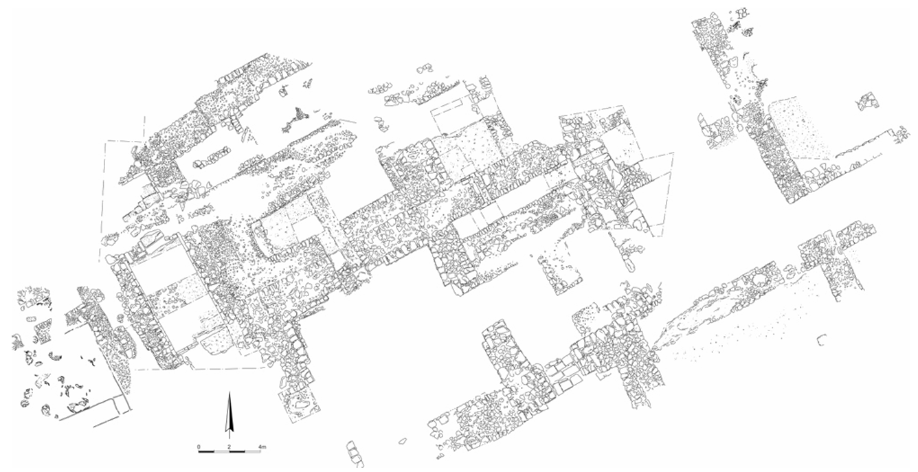 Figure 2
Plan of Areas D-West and D-West East
Yasur-Landau et al. (2013) - Fig. 3 Plan of northern
storage room in Area D-West from Yasur-Landau et al. (2013)
 Figure 3
Plan of northern storage room in Area D-West, with entrances from northwest and southeast
Yasur-Landau et al. (2013) - Fig. 2 Plan of the
northwestern corner of the palace and adjacent features from Yasur-Landau et al. (2012)
 Figure 2
Plan of the northwestern corner of the palace and adjacent features, with wall numbers
(drawn by Dov Porotsky)
Yasur-Landau et al. (2012) - Fig. 2 Plan of the
southern and northern storage complexes after the 2015 season from Yasur-Landau et al. (2012)
 Figure 2
Plan of the southern and northern storage complexes after the 20155 season. Feature labels are abbreviated as follows
- F = Floor
- I = Installation
- L = Locus
- R = Room
- W = Wall
(drawing by S. Pirsky)
Yasur-Landau et al. (2012)
- Fig. 2 Plan of Areas
D-West and D-West East from Yasur-Landau et al. (2013)
Figure 2
Plan of Areas D-West and D-West East
Yasur-Landau et al. (2013) - Fig. 3 Plan of northern
storage room in Area D-West from Yasur-Landau et al. (2013)
Figure 3
Plan of northern storage room in Area D-West, with entrances from northwest and southeast
Yasur-Landau et al. (2013) - Fig. 2 Plan of the
northwestern corner of the palace and adjacent features from Yasur-Landau et al. (2012)
Figure 2
Plan of the northwestern corner of the palace and adjacent features, with wall numbers
(drawn by Dov Porotsky)
Yasur-Landau et al. (2012) - Fig. 2 Plan of the
southern and northern storage complexes after the 2015 season from Yasur-Landau et al. (2012)
Figure 2
Plan of the southern and northern storage complexes after the 2015 season. Feature labels are abbreviated as follows
- F = Floor
- I = Installation
- L = Locus
- R = Room
- W = Wall
(drawing by S. Pirsky)
YYasur-Landau et al. (2012)
- from Lazar et al. (2020)
 Table 1
Potential (off-fault) Earthquake Archaeological Effects (PEAEs)
(after [11]) and corresponding findings in Kabri
Lazar et al. (2020)
- Fig. 3a Aerial View of
the Orthostat Building from Lazar et al. (2020)
 Figure 3a
The Orthostat Building. Each black or white segment on the scale-sticks represents 10 cm. Aerial view showing the Main Room (MR), Back Room (BR), and Trench (F), which is denoted by dashed red lines. Notice that the southern side of the trench is partially obscured by a large stone block, whose flat upper side would have once served as a threshold leading into the back room, but which has now collapsed into the trench.
Photo: Griffin Aerial Imaging.
Lazar et al. (2020) - Fig. 3b backroom (2411)
of the Orthostat Building covered in collapsed mudbrick and plaster from Lazar et al. (2020)
 Figure 3b
The Orthostat Building. Each black or white segment on the scale-sticks represents 10 cm. The backroom (2411) covered in collapsed mudbrick and plaster.
Lazar et al. (2020) - Fig. 3c Displaced floor
in the Orthostat Building from Lazar et al. (2020)
 Figure 3c
The Orthostat Building. Each black or white segment on the scale-sticks represents 10 cm. Step or displacement in the floor of the Orthostat Building, just inside the entrance. One of the offset orthostats is visible at the top of the image.
Lazar et al. (2020) - Fig. 3d Main Room of
the Orthostat Building showing unbroken warped cross-walls and tilted and collapsed walls from Lazar et al. (2020)
 Figure 3d
The Orthostat Building. Each black or white segment on the scale-sticks represents 10 cm. The Main Room looking south and showing unbroken warped cross-walls; i.e., with a rise visible in the height of the walls. At the bottom of the image, wall 2404 and the threshold leading into the back room are visibly collapsed and tilting into the trench.
Lazar et al. (2020) - Fig. 3e Broken and
sloping plaster floor in the backroom of the Orthostat Building from Lazar et al. (2020)
 Figure 3e
The backroom cleared of all rubble shown in Fig 3b, showing the broken and sloping plaster floor.
Lazar et al. (2020) - Fig. 4a Aerial View of
the wine cellar from Lazar et al. (2020)
 Figure 4a
The wine cellar (Room 2440 in the Southern Storage Complex). Aerial view showing the Southern Storage Complex (SSC), the Northern Storage Complex (NSC; blue dashed box) and the Trench (T; also denoted by the dashed red lines). Green star marks the approximate location of Fig 5a. Yellow star marks the approximate location of Fig 5b.
Photo: Griffin Aerial Imaging.
Lazar et al. (2020) - Fig. 4b Room 2440 showing
~48 in situ pithoi and warped eastern wall from Lazar et al. (2020)
 Figure 4b
The wine cellar (Room 2440 in the Southern Storage Complex). Room 2440 showing ~48 pithoi found in situ. Note the warping in the eastern wall of the room (W2441 Fig 2).
Lazar et al. (2020) - Fig. 4c Room 2440 after
being cleared of the pithoi from Lazar et al. (2020)
 Figure 4c
The wine cellar (Room 2440 in the Southern Storage Complex). Room 2440 after being cleared of the pithoi.
Lazar et al. (2020) - Fig. 4d Displaced wall
W2443 in Room 2440 from Lazar et al. (2020)
 Figure 4d
The wine cellar (Room 2440 in the Southern Storage Complex). Displaced wall W2443 in Room 2440 marked by blue dashed box on Fig 2.
Lazar et al. (2020) - Fig. 5a Collapse in
Room 3306 from Lazar et al. (2020)
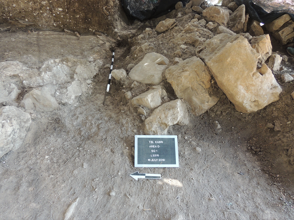 Figure 5a
Field photos of collapse into the trench. Photo from above in Room 3306 of the Northern Storage Complex. Left side of the image shows the trench. Right side of image shows pithoi that appear to have rolled southwards towards the trench and the collapse of the plaster floor into this feature. Arrow points to north. Each section of the scale-sticks corresponds to 10 cm.
Lazar et al. (2020) - Fig. 5b Broken Pottery
and Collapse in Room 3306 from Lazar et al. (2020)
 Figure 5b
Field photos of collapse into the trench. Photo from above in Room 3306 of the Northern Storage Complex. Left side of the image shows the trench. Right side of image shows pithoi that appear to have rolled southwards towards the trench and the collapse of the plaster floor into this feature. Arrow points to north. Each section of the scale-sticks corresponds to 10 cm.
Lazar et al. (2020)
- Fig. 3a Aerial View of
the Orthostat Building from Lazar et al. (2020)
Figure 3a
The Orthostat Building. Each black or white segment on the scale-sticks represents 10 cm. Aerial view showing the Main Room (MR), Back Room (BR), and Trench (F), which is denoted by dashed red lines. Notice that the southern side of the trench is partially obscured by a large stone block, whose flat upper side would have once served as a threshold leading into the back room, but which has now collapsed into the trench.
Photo: Griffin Aerial Imaging.
Lazar et al. (2020) - Fig. 3b backroom (2411)
of the Orthostat Building covered in collapsed mudbrick and plaster from Lazar et al. (2020)
Figure 3b
The Orthostat Building. Each black or white segment on the scale-sticks represents 10 cm. The backroom (2411) covered in collapsed mudbrick and plaster.
Lazar et al. (2020) - Fig. 3c Displaced floor
in the Orthostat Building from Lazar et al. (2020)
Figure 3c
The Orthostat Building. Each black or white segment on the scale-sticks represents 10 cm. Step or displacement in the floor of the Orthostat Building, just inside the entrance. One of the offset orthostats is visible at the top of the image.
Lazar et al. (2020) - Fig. 3d Main Room of
the Orthostat Building showing unbroken warped cross-walls and tilted and collapsed walls from Lazar et al. (2020)
Figure 3d
The Orthostat Building. Each black or white segment on the scale-sticks represents 10 cm. The Main Room looking south and showing unbroken warped cross-walls; i.e., with a rise visible in the height of the walls. At the bottom of the image, wall 2404 and the threshold leading into the back room are visibly collapsed and tilting into the trench.
Lazar et al. (2020) - Fig. 3e Broken and
sloping plaster floor in the backroom of the Orthostat Building from Lazar et al. (2020)
Figure 3e
The backroom cleared of all rubble shown in Fig 3b, showing the broken and sloping plaster floor.
Lazar et al. (2020) - Fig. 4a Aerial View of
the wine cellar from Lazar et al. (2020)
Figure 4a
The wine cellar (Room 2440 in the Southern Storage Complex). Aerial view showing the Southern Storage Complex (SSC), the Northern Storage Complex (NSC; blue dashed box) and the Trench (T; also denoted by the dashed red lines). Green star marks the approximate location of Fig 5a. Yellow star marks the approximate location of Fig 5b.
Photo: Griffin Aerial Imaging.
Lazar et al. (2020) - Fig. 4b Room 2440 showing
~48 in situ pithoi and warped eastern wall from Lazar et al. (2020)
Figure 4b
The wine cellar (Room 2440 in the Southern Storage Complex). Room 2440 showing ~48 pithoi found in situ. Note the warping in the eastern wall of the room (W2441 Fig 2).
Lazar et al. (2020) - Fig. 4c Room 2440 after
being cleared of the pithoi from Lazar et al. (2020)
Figure 4c
The wine cellar (Room 2440 in the Southern Storage Complex). Room 2440 after being cleared of the pithoi.
Lazar et al. (2020) - Fig. 4d Displaced wall
W2443 in Room 2440 from Lazar et al. (2020)
Figure 4d
The wine cellar (Room 2440 in the Southern Storage Complex). Displaced wall W2443 in Room 2440 marked by blue dashed box on Fig 2.
Lazar et al. (2020) - Fig. 5a Collapse in
Room 3306 from Lazar et al. (2020)
Figure 5a
Field photos of collapse into the trench. Photo from above in Room 3306 of the Northern Storage Complex. Left side of the image shows the trench. Right side of image shows pithoi that appear to have rolled southwards towards the trench and the collapse of the plaster floor into this feature. Arrow points to north. Each section of the scale-sticks corresponds to 10 cm.
Lazar et al. (2020) - Fig. 5b Broken Pottery
and Collapse in Room 3306 from Lazar et al. (2020)
Figure 5b
Field photos of collapse into the trench. Photo from above in Room 3306 of the Northern Storage Complex. Left side of the image shows the trench. Right side of image shows pithoi that appear to have rolled southwards towards the trench and the collapse of the plaster floor into this feature. Arrow points to north. Each section of the scale-sticks corresponds to 10 cm.
Lazar et al. (2020)
- Fig. S1a Field photograph
demonstrating sampling of bulk sediments from Wall W2450 and its surrounding from Lazar et al. (2020)
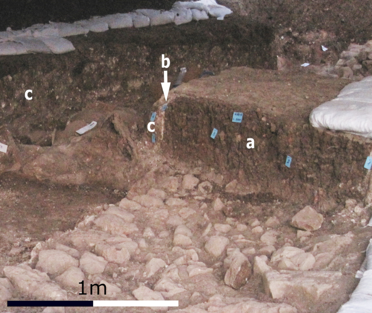 Figure S1a
Field photographs demonstrating field sampling of bulk sediments. (a) Wall W2450 and its surrounding. The blue tags indicate bulk sample positions.
- mud bricks in the wall
- white plaster lining the wall
- fill deposits next to the wall associated with several pithoi on the floor next to the wall. Note the white-speckled nature of the fill deposits, due to abundant plaster fragments
Lazar et al. (2020) - Fig. S1b Field photograph
demonstrating sampling of block samples in Room 2520 from Lazar et al. (2020)
 Figure S1b
Field photographs demonstrating field sampling of bulk sediments. (b) Field photograph exemplifying sampling of block samples in Room 2520.
- Phase III floor
- ceramic walls of a storage jar lying on the floor and sectioned in situ
- fill deposit
Lazar et al. (2020) - Fig. 6a Thin section
of a mudbrick from a Phase III wall from Lazar et al. (2020)
 Figure 6a
Results of micromorphology analysis. (a) Scan of thin section of a mudbrick from a Phase III wall (sample KAB-2450.5 in S2 Table).
Lazar et al. (2020) - Fig. 6b Microphotograph
of a Phase III mudbrick from Lazar et al. (2020)
 Figure 6b
Results of micromorphology analysis. (b) Microphotograph of a Phase III mudbrick (sample KAB-2450.5 in S2 Table).
Lazar et al. (2020) - Fig. 6c Thin section
of the fill deposit (5–11 cm) above the palaces’ Phase III floor from Lazar et al. (2020)
 Figure 6c
Results of micromorphology analysis. (c) Scan of thin section of the fill deposit (5–11 cm) above the palaces’ Phase III floor (sample KAB-B2 in S2 Table). The red particles are pottery sherds.
Lazar et al. (2020) - Fig. 6d Microphotograph
showing the general appearance of the fill deposit shown in 6 (c) from Lazar et al. (2020)
 Figure 6d
Results of micromorphology analysis.floor (d) Microphotograph showing the general appearance of the fill deposit shown in (c).
Lazar et al. (2020) - Fig. 6e Field photo showing
the Phase III plaster floor of Room 2553 and the fill deposit covering it from Lazar et al. (2020)
 Figure 6e
Results of micromorphology analysis. (e) Field photo showing the Phase III plaster floor of Room 2553 and the fill deposit covering it.
Lazar et al. (2020) - Fig. 6f Thin section
of the contact shown in 6 (e) from Lazar et al. (2020)
 Figure 6f
Results of micromorphology analysis. (f) Scan of thin section of the contact shown in (e) (sample KAB-2603.13 in S2 Table).
Lazar et al. (2020) - Fig. 6g Microphotograph
showing the contact between the floor and sediment lying directly on it shown in 6 (f) from Lazar et al. (2020)
 Figure 6g
Results of micromorphology analysis. (g) Microphotograph showing the contact between the floor and sediment lying directly on it shown in (f).
Lazar et al. (2020)
- Fig. S1a Field photograph
demonstrating sampling of bulk sediments from Wall W2450 and its surrounding from Lazar et al. (2020)
Figure S1a
Field photographs demonstrating field sampling of bulk sediments. (a) Wall W2450 and its surrounding. The blue tags indicate bulk sample positions.
- mud bricks in the wall
- white plaster lining the wall
- fill deposits next to the wall associated with several pithoi on the floor next to the wall. Note the white-speckled nature of the fill deposits, due to abundant plaster fragments
Lazar et al. (2020) - Fig. S1b Field photograph
demonstrating sampling of block samples in Room 2520 from Lazar et al. (2020)
Figure S1b
Field photographs demonstrating field sampling of bulk sediments. (b) Field photograph exemplifying sampling of block samples in Room 2520.
- Phase III floor
- ceramic walls of a storage jar lying on the floor and sectioned in situ
- fill deposit
Lazar et al. (2020) - Fig. 6a Thin section
of a mudbrick from a Phase III wall from Lazar et al. (2020)
Figure 6a
Results of micromorphology analysis. (a) Scan of thin section of a mudbrick from a Phase III wall (sample KAB-2450.5 in S2 Table).
Lazar et al. (2020) - Fig. 6b Microphotograph
of a Phase III mudbrick from Lazar et al. (2020)
Figure 6b
Results of micromorphology analysis. (b) Microphotograph of a Phase III mudbrick (sample KAB-2450.5 in S2 Table).
Lazar et al. (2020) - Fig. 6c Thin section
of the fill deposit (5–11 cm) above the palaces’ Phase III floor from Lazar et al. (2020)
Figure 6c
Results of micromorphology analysis. (c) Scan of thin section of the fill deposit (5–11 cm) above the palaces’ Phase III floor (sample KAB-B2 in S2 Table). The red particles are pottery sherds.
Lazar et al. (2020) - Fig. 6d Microphotograph
showing the general appearance of the fill deposit shown in 6 (c) from Lazar et al. (2020)
Figure 6d
Results of micromorphology analysis.floor (d) Microphotograph showing the general appearance of the fill deposit shown in (c).
Lazar et al. (2020) - Fig. 6e Field photo showing
the Phase III plaster floor of Room 2553 and the fill deposit covering it from Lazar et al. (2020)
Figure 6e
Results of micromorphology analysis. (e) Field photo showing the Phase III plaster floor of Room 2553 and the fill deposit covering it.
Lazar et al. (2020) - Fig. 6f Thin section
of the contact shown in 6 (e) from Lazar et al. (2020)
Figure 6f
Results of micromorphology analysis. (f) Scan of thin section of the contact shown in (e) (sample KAB-2603.13 in S2 Table).
Lazar et al. (2020) - Fig. 6g Microphotograph
showing the contact between the floor and sediment lying directly on it shown in 6 (f) from Lazar et al. (2020)
Figure 6g
Results of micromorphology analysis. (g) Microphotograph showing the contact between the floor and sediment lying directly on it shown in (f).
Lazar et al. (2020)
 Table 1
Stratigraphic overview of the Middle Bronze Age phases at Tel Kabri
Yasur-Landau et al. (2018)
... Despite the presence of contemporary archaeological sites near Kabri, such as Tel Hazor and Acco (Fig 1b), there have been no reports from these extensively excavated sites of evidence for MB II earthquakes. This could be due to a number of factors, such as the difficulty in recognizing the expression of ground shaking due to earthquakes in structures that were built of mudbrick.
JW: There is some Bronze Age
 Bronze Age (Canaanite) Wall Collapse at Tel Hazor
photo by Jefferson Williams from April 2023
| Effect | Location | Image(s) | Description |
|---|---|---|---|
| Collapsed Walls | Fig. 2 Phase III plan showing orthostat building and storage complex outlined by dotted black lines
Plan of Phase III at Tel Kabri.
Lazar et al. (2020) Fig. 3a - Main and Back rooms of the Orthostat Building (Rooms 2372 and 2411 respectively)
Figure 3aThe Orthostat Building. Each black or white segment on the scale-sticks represents 10 cm. Aerial view showing the Main Room (MR), Back Room (BR), and Trench (F), which is denoted by dashed red lines. Notice that the southern side of the trench is partially obscured by a large stone block, whose flat upper side would have once served as a threshold leading into the back room, but which has now collapsed into the trench. Photo: Griffin Aerial Imaging. Lazar et al. (2020) Fig. 4a all the rooms of the Storage Complex (e.g. Room 2440 aka SSC; Room 3306 aka NSC)
Figure 4aThe wine cellar (Room 2440 in the Southern Storage Complex). Aerial view showing the Southern Storage Complex (SSC), the Northern Storage Complex (NSC; blue dashed box) and the Trench (T; also denoted by the dashed red lines). Green star marks the approximate location of Fig 5a. Yellow star marks the approximate location of Fig 5b. Photo: Griffin Aerial Imaging. Lazar et al. (2020) |
Fig. 3b - Back Room 2411 of the Orthostat Building
Figure 3b The Orthostat Building. Each black or white segment on the scale-sticks represents 10 cm. The backroom (2411) covered in collapsed mudbrick and plaster. Lazar et al. (2020) Fig. 3d - Main Room 2372 of the Orthostat Building
Figure 3dThe Orthostat Building. Each black or white segment on the scale-sticks represents 10 cm. The Main Room looking south and showing unbroken warped cross-walls; i.e., with a rise visible in the height of the walls. At the bottom of the image, wall 2404 and the threshold leading into the back room are visibly collapsed and tilting into the trench. Lazar et al. (2020) Fig. 4b - Room 2440 (aka SSC) in the Storage Complex
Figure 4bThe wine cellar (Room 2440 in the Southern Storage Complex). Room 2440 showing ~48 pithoi found in situ. Note the warping in the eastern wall of the room (W2441 Fig 2). Lazar et al. (2020) Fig. 5a - Room 3306 (aka NSC) in the Storage Complex
Figure 5aField photos of collapse into the trench. Photo from above in Room 3306 of the Northern Storage Complex. Left side of the image shows the trench. Right side of image shows pithoi that appear to have rolled southwards towards the trench and the collapse of the plaster floor into this feature. Arrow points to north. Each section of the scale-sticks corresponds to 10 cm. Lazar et al. (2020) |
|
|
Fig. 2 Phase III plan showing orthostat building and storage complex outlined by dotted black lines
Plan of Phase III at Tel Kabri.
Lazar et al. (2020) Fig. 3a - Main and Back rooms of the Orthostat Building (Rooms 2372 and 2411 respectively)
Figure 3aThe Orthostat Building. Each black or white segment on the scale-sticks represents 10 cm. Aerial view showing the Main Room (MR), Back Room (BR), and Trench (F), which is denoted by dashed red lines. Notice that the southern side of the trench is partially obscured by a large stone block, whose flat upper side would have once served as a threshold leading into the back room, but which has now collapsed into the trench. Photo: Griffin Aerial Imaging. Lazar et al. (2020) Fig. 4a all the rooms of the Storage Complex (e.g. Room 2440 aka SSC; Room 3306 aka NSC)
Figure 4aThe wine cellar (Room 2440 in the Southern Storage Complex). Aerial view showing the Southern Storage Complex (SSC), the Northern Storage Complex (NSC; blue dashed box) and the Trench (T; also denoted by the dashed red lines). Green star marks the approximate location of Fig 5a. Yellow star marks the approximate location of Fig 5b. Photo: Griffin Aerial Imaging. Lazar et al. (2020) |
Fig. 4d Displaced wall W2443 in Room 2440 of the Storage Complex
Figure 4d The wine cellar (Room 2440 in the Southern Storage Complex). Displaced wall W2443 in Room 2440 marked by blue dashed box on Fig 2. Lazar et al. (2020) Fig. 3d Main Room of the Orthostat Building showing unbroken warped cross-walls and tilted and collapsed walls
Figure 3dThe Orthostat Building. Each black or white segment on the scale-sticks represents 10 cm. The Main Room looking south and showing unbroken warped cross-walls; i.e., with a rise visible in the height of the walls. At the bottom of the image, wall 2404 and the threshold leading into the back room are visibly collapsed and tilting into the trench. Lazar et al. (2020) |
|
| Folded/Faulted Floor Surfaces (Fractures, Folds, and Popups on regular pavements) | Fig. 2 Phase III plan showing orthostat building and storage complex outlined by dotted black lines
Plan of Phase III at Tel Kabri.
Lazar et al. (2020) Fig. 3a - Main and Back rooms of the Orthostat Building (Rooms 2372 and 2411 respectively)
Figure 3aThe Orthostat Building. Each black or white segment on the scale-sticks represents 10 cm. Aerial view showing the Main Room (MR), Back Room (BR), and Trench (F), which is denoted by dashed red lines. Notice that the southern side of the trench is partially obscured by a large stone block, whose flat upper side would have once served as a threshold leading into the back room, but which has now collapsed into the trench. Photo: Griffin Aerial Imaging. Lazar et al. (2020) Fig. 4a all the rooms of the Storage Complex (e.g. Room 2440 aka SSC; Room 3306 aka NSC)
Figure 4aThe wine cellar (Room 2440 in the Southern Storage Complex). Aerial view showing the Southern Storage Complex (SSC), the Northern Storage Complex (NSC; blue dashed box) and the Trench (T; also denoted by the dashed red lines). Green star marks the approximate location of Fig 5a. Yellow star marks the approximate location of Fig 5b. Photo: Griffin Aerial Imaging. Lazar et al. (2020) |
Fig. 3c Displaced floor in Room 2372 of Orthostat Building
Figure 3c The Orthostat Building. Each black or white segment on the scale-sticks represents 10 cm. Step or displacement in the floor of the Orthostat Building, just inside the entrance. One of the offset orthostats is visible at the top of the image. Lazar et al. (2020) Fig. 3d - northern wall (W2404) in Main Room 2372 of the Orthostat Building
Figure 3dThe Orthostat Building. Each black or white segment on the scale-sticks represents 10 cm. The Main Room looking south and showing unbroken warped cross-walls; i.e., with a rise visible in the height of the walls. At the bottom of the image, wall 2404 and the threshold leading into the back room are visibly collapsed and tilting into the trench. Lazar et al. (2020) Fig. 3e - Broken and sloping plaster floor in the backroom (2411) of the Orthostat Building
Figure 3eThe backroom cleared of all rubble shown in Fig 3b, showing the broken and sloping plaster floor. Lazar et al. (2020) Fig. 4b Room 2440
Figure 4bThe wine cellar (Room 2440 in the Southern Storage Complex). Room 2440 showing ~48 pithoi found in situ. Note the warping in the eastern wall of the room (W2441 Fig 2). Lazar et al. (2020) Fig. 4c Room 2440
Figure 4cThe wine cellar (Room 2440 in the Southern Storage Complex). Room 2440 after being cleared of the pithoi. Lazar et al. (2020) |
|
| Pockmarked Floor (Impact Block Marks) | Fig. 2 Phase III plan showing orthostat building and storage complex outlined by dotted black lines
Plan of Phase III at Tel Kabri.
Lazar et al. (2020) Fig. 3a - Main and Back rooms of the Orthostat Building (Rooms 2372 and 2411 respectively)
Figure 3aThe Orthostat Building. Each black or white segment on the scale-sticks represents 10 cm. Aerial view showing the Main Room (MR), Back Room (BR), and Trench (F), which is denoted by dashed red lines. Notice that the southern side of the trench is partially obscured by a large stone block, whose flat upper side would have once served as a threshold leading into the back room, but which has now collapsed into the trench. Photo: Griffin Aerial Imaging. Lazar et al. (2020) Fig. 4a Rooms of the Storage Complex (e.g. Room 2440 aka SSC; Room 3306 aka NSC)
Figure 4aThe wine cellar (Room 2440 in the Southern Storage Complex). Aerial view showing the Southern Storage Complex (SSC), the Northern Storage Complex (NSC; blue dashed box) and the Trench (T; also denoted by the dashed red lines). Green star marks the approximate location of Fig 5a. Yellow star marks the approximate location of Fig 5b. Photo: Griffin Aerial Imaging. Lazar et al. (2020) |
|
|
| Smashed Pottery | Fig. 2 Phase III plan showing orthostat building and storage complex outlined by dotted black lines
Plan of Phase III at Tel Kabri.
Lazar et al. (2020) Fig. 3a - Main and Back rooms of the Orthostat Building (Rooms 2372 and 2411 respectively)
Figure 3aThe Orthostat Building. Each black or white segment on the scale-sticks represents 10 cm. Aerial view showing the Main Room (MR), Back Room (BR), and Trench (F), which is denoted by dashed red lines. Notice that the southern side of the trench is partially obscured by a large stone block, whose flat upper side would have once served as a threshold leading into the back room, but which has now collapsed into the trench. Photo: Griffin Aerial Imaging. Lazar et al. (2020) Fig. 4a Rooms of the Storage Complex (e.g. Room 2440 aka SSC; Room 3306 aka NSC)
Figure 4aThe wine cellar (Room 2440 in the Southern Storage Complex). Aerial view showing the Southern Storage Complex (SSC), the Northern Storage Complex (NSC; blue dashed box) and the Trench (T; also denoted by the dashed red lines). Green star marks the approximate location of Fig 5a. Yellow star marks the approximate location of Fig 5b. Photo: Griffin Aerial Imaging. Lazar et al. (2020) |
Fig. 3b - Back Room 2411 of the Orthostat Building
Figure 3b The Orthostat Building. Each black or white segment on the scale-sticks represents 10 cm. The backroom (2411) covered in collapsed mudbrick and plaster. Lazar et al. (2020) Fig. 4b - Room 2440 (aka SSC) in the Storage Complex
Figure 4bThe wine cellar (Room 2440 in the Southern Storage Complex). Room 2440 showing ~48 pithoi found in situ. Note the warping in the eastern wall of the room (W2441 Fig 2). Lazar et al. (2020) |
|
| Fallen Objects and Fallen Pottery | Fig. 2 Rooms 690 and 740 and Stairwell 694
Plan of Phase III at Tel Kabri.
Lazar et al. (2020) |
Fig. 5b Broken Pottery and Collapse in Room 3306 of the Northern Storage Complex
Figure 5b Field photos of collapse into the trench. Photo from above in Room 3306 of the Northern Storage Complex. Left side of the image shows the trench. Right side of image shows pithoi that appear to have rolled southwards towards the trench and the collapse of the plaster floor into this feature. Arrow points to north. Each section of the scale-sticks corresponds to 10 cm. Lazar et al. (2020) |
|
| Oriented Fallen Objects | Fig. 2 Rooms 2520, 2533, and 2546
Plan of Phase III at Tel Kabri.
Lazar et al. (2020) |
|
|
| Trench Formation (fault scarp) | Fig. 1b Fault map of the Galilee Area
Compiled map of faults in the Galilee area. Thin black lines indicate faults that appear on the 1:200000 geological map Colored lines mark Quaternary faults :
Black Lines Reprinted from [22] under a CC BY license, with permission from [Geological Survey of Israel], original copyright [1998]). Colored Lines Reprinted from [23] under a CC BY license, with permission from [Geological Survey of Israel], original copyright [2018]). Lazar et al. (2020) Fig. 1c Geological map of the area around the mound of Tel Kabri
Figure 1cGeological map of the area showing the mound of Tel Kabri and its associated potentially active tectonic fault. Colored lines mark different interpretations for the Kabri fault:
Blue dots mark the location of the four springs located in the vicinity of Tel Kabri. Light blue rectangle marks the location of the study area shown in Fig 2. (Reprinted from [22] under a CC BY license, with permission from [Geological Survey of Israel], original copyright [1998]) Lazar et al. (2020) Fig. 2 Phase III plan showing trench outlined by dotted red lines
Plan of Phase III at Tel Kabri.
Lazar et al. (2020) Fig. 3a - Main and Back rooms of the Orthostat Building (Rooms 2372 and 2411 respectively) showing trench outlined by dotted red lines
Figure 3aThe Orthostat Building. Each black or white segment on the scale-sticks represents 10 cm. Aerial view showing the Main Room (MR), Back Room (BR), and Trench (F), which is denoted by dashed red lines. Notice that the southern side of the trench is partially obscured by a large stone block, whose flat upper side would have once served as a threshold leading into the back room, but which has now collapsed into the trench. Photo: Griffin Aerial Imaging. Lazar et al. (2020) Fig. 4a all the rooms of the Storage Complex (e.g. Room 2440 aka SSC; Room 3306 aka NSC) showing trench outlined by dotted red lines
Figure 4aThe wine cellar (Room 2440 in the Southern Storage Complex). Aerial view showing the Southern Storage Complex (SSC), the Northern Storage Complex (NSC; blue dashed box) and the Trench (T; also denoted by the dashed red lines). Green star marks the approximate location of Fig 5a. Yellow star marks the approximate location of Fig 5b. Photo: Griffin Aerial Imaging. Lazar et al. (2020) |
Fig. 3e - Broken and sloping plaster floor in the backroom (2411) of the Orthostat Building
Figure 3e The backroom cleared of all rubble shown in Fig 3b, showing the broken and sloping plaster floor. Lazar et al. (2020) Fig. 4d Displaced wall W2443 in Room 2440 of the Storage Complex
Figure 4dThe wine cellar (Room 2440 in the Southern Storage Complex). Displaced wall W2443 in Room 2440 marked by blue dashed box on Fig 2. Lazar et al. (2020) Fig. 5a - Room 3306 (aka NSC) in the Storage Complex
Figure 5aField photos of collapse into the trench. Photo from above in Room 3306 of the Northern Storage Complex. Left side of the image shows the trench. Right side of image shows pithoi that appear to have rolled southwards towards the trench and the collapse of the plaster floor into this feature. Arrow points to north. Each section of the scale-sticks corresponds to 10 cm. Lazar et al. (2020) Fig. 5b Broken Pottery and Collapse in Room 3306 of the Northern Storage Complex
Figure 5bField photos of collapse into the trench. Photo from above in Room 3306 of the Northern Storage Complex. Left side of the image shows the trench. Right side of image shows pithoi that appear to have rolled southwards towards the trench and the collapse of the plaster floor into this feature. Arrow points to north. Each section of the scale-sticks corresponds to 10 cm. Lazar et al. (2020) |
|
| Debris | Fig. 2 Phase III plan showing trench outlined by dotted red lines
Plan of Phase III at Tel Kabri.
Lazar et al. (2020) Fig. 4a all the rooms of the Storage Complex (e.g. Room 2440 aka SSC; Room 3306 aka NSC) showing trench outlined by dotted red lines
Figure 4aThe wine cellar (Room 2440 in the Southern Storage Complex). Aerial view showing the Southern Storage Complex (SSC), the Northern Storage Complex (NSC; blue dashed box) and the Trench (T; also denoted by the dashed red lines). Green star marks the approximate location of Fig 5a. Yellow star marks the approximate location of Fig 5b. Photo: Griffin Aerial Imaging. Lazar et al. (2020) Fig. S1a Field photograph demonstrating sampling of bulk sediments from Wall W2450 and its surrounding
Figure S1aField photographs demonstrating field sampling of bulk sediments. (a) Wall W2450 and its surrounding. The blue tags indicate bulk sample positions.
Lazar et al. (2020) Fig. S1b Field photograph demonstrating sampling of block samples in Room 2520
Figure S1bField photographs demonstrating field sampling of bulk sediments. (b) Field photograph exemplifying sampling of block samples in Room 2520.
Lazar et al. (2020) |
Fig. 6c Thin section of the fill deposit (5–11 cm) above the palaces’ Phase III floor
Figure 6c Results of micromorphology analysis. (c) Scan of thin section of the fill deposit (5–11 cm) above the palaces’ Phase III floor (sample KAB-B2 in S2 Table). The red particles are pottery sherds. Lazar et al. (2020) Fig. 6d Microphotograph showing the general appearance of the fill deposit shown in 6 (c)
Figure 6dResults of micromorphology analysis.floor (d) Microphotograph showing the general appearance of the fill deposit shown in (c). Lazar et al. (2020) Fig. 6e Field photo showing the Phase III plaster floor of Room 2553 and the fill deposit covering it
Figure 6eResults of micromorphology analysis. (e) Field photo showing the Phase III plaster floor of Room 2553 and the fill deposit covering it. Lazar et al. (2020) Fig. 6f Thin section of the contact shown in 6 (e)
Figure 6fResults of micromorphology analysis. (f) Scan of thin section of the contact shown in (e) (sample KAB-2603.13 in S2 Table). Lazar et al. (2020) Fig. 6g Microphotograph showing the contact between the floor and sediment lying directly on it shown in 6 (f)
Figure 6gResults of micromorphology analysis. (g) Microphotograph showing the contact between the floor and sediment lying directly on it shown in (f). Lazar et al. (2020) |
|
-
Potential Earthquake Archeological Effects chart
of Jusseret et al. (2013)
 Potential earthquake archaeological effects (PEAEs) on Minoan remains. Adapted from Rodríguez-Pascua et al. (2011) and
Macdonald (2001), completed by Warren (1991), Knappett and Cunningham (2003), and Rucker and Niemi (2010). See text for further
explanation.
Potential earthquake archaeological effects (PEAEs) on Minoan remains. Adapted from Rodríguez-Pascua et al. (2011) and
Macdonald (2001), completed by Warren (1991), Knappett and Cunningham (2003), and Rucker and Niemi (2010). See text for further
explanation.
Jusseret et al. (2013) - from Lazar et al. (2020)
Table 1Potential (off-fault) Earthquake Archaeological Effects (PEAEs)
(after [11]) and corresponding findings in Kabri
Lazar et al. (2020)
- Modified by JW from Figure 2 from Lazar et al. (2020)
 Deformation Map
Modified by JW from Figure 2 from Lazar et al. (2020)
-
Earthquake Archeological Effects chart
of Rodríguez-Pascua et al (2013: 221-224)
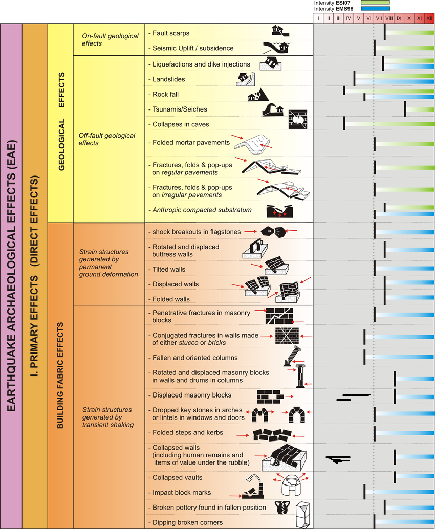 Earthquake Archeological Effects (EAE)
Rodríguez-Pascua et al (2013: 221-224)
| Effect | Location | Image(s) | Description | Intensity |
|---|---|---|---|---|
| Collapsed Walls | Fig. 2 Phase III plan showing orthostat building and storage complex outlined by dotted black lines
Plan of Phase III at Tel Kabri.
Lazar et al. (2020) Fig. 3a - Main and Back rooms of the Orthostat Building (Rooms 2372 and 2411 respectively)
Figure 3aThe Orthostat Building. Each black or white segment on the scale-sticks represents 10 cm. Aerial view showing the Main Room (MR), Back Room (BR), and Trench (F), which is denoted by dashed red lines. Notice that the southern side of the trench is partially obscured by a large stone block, whose flat upper side would have once served as a threshold leading into the back room, but which has now collapsed into the trench. Photo: Griffin Aerial Imaging. Lazar et al. (2020) Fig. 4a all the rooms of the Storage Complex (e.g. Room 2440 aka SSC; Room 3306 aka NSC)
Figure 4aThe wine cellar (Room 2440 in the Southern Storage Complex). Aerial view showing the Southern Storage Complex (SSC), the Northern Storage Complex (NSC; blue dashed box) and the Trench (T; also denoted by the dashed red lines). Green star marks the approximate location of Fig 5a. Yellow star marks the approximate location of Fig 5b. Photo: Griffin Aerial Imaging. Lazar et al. (2020) |
Fig. 3b - Back Room 2411 of the Orthostat Building
Figure 3b The Orthostat Building. Each black or white segment on the scale-sticks represents 10 cm. The backroom (2411) covered in collapsed mudbrick and plaster. Lazar et al. (2020) Fig. 3d - Main Room 2372 of the Orthostat Building
Figure 3dThe Orthostat Building. Each black or white segment on the scale-sticks represents 10 cm. The Main Room looking south and showing unbroken warped cross-walls; i.e., with a rise visible in the height of the walls. At the bottom of the image, wall 2404 and the threshold leading into the back room are visibly collapsed and tilting into the trench. Lazar et al. (2020) Fig. 4b - Room 2440 (aka SSC) in the Storage Complex
Figure 4bThe wine cellar (Room 2440 in the Southern Storage Complex). Room 2440 showing ~48 pithoi found in situ. Note the warping in the eastern wall of the room (W2441 Fig 2). Lazar et al. (2020) Fig. 5a - Room 3306 (aka NSC) in the Storage Complex
Figure 5aField photos of collapse into the trench. Photo from above in Room 3306 of the Northern Storage Complex. Left side of the image shows the trench. Right side of image shows pithoi that appear to have rolled southwards towards the trench and the collapse of the plaster floor into this feature. Arrow points to north. Each section of the scale-sticks corresponds to 10 cm. Lazar et al. (2020) |
|
VIII+ |
|
Fig. 2 Phase III plan showing orthostat building and storage complex outlined by dotted black lines
Plan of Phase III at Tel Kabri.
Lazar et al. (2020) Fig. 3a - Main and Back rooms of the Orthostat Building (Rooms 2372 and 2411 respectively)
Figure 3aThe Orthostat Building. Each black or white segment on the scale-sticks represents 10 cm. Aerial view showing the Main Room (MR), Back Room (BR), and Trench (F), which is denoted by dashed red lines. Notice that the southern side of the trench is partially obscured by a large stone block, whose flat upper side would have once served as a threshold leading into the back room, but which has now collapsed into the trench. Photo: Griffin Aerial Imaging. Lazar et al. (2020) Fig. 4a all the rooms of the Storage Complex (e.g. Room 2440 aka SSC; Room 3306 aka NSC)
Figure 4aThe wine cellar (Room 2440 in the Southern Storage Complex). Aerial view showing the Southern Storage Complex (SSC), the Northern Storage Complex (NSC; blue dashed box) and the Trench (T; also denoted by the dashed red lines). Green star marks the approximate location of Fig 5a. Yellow star marks the approximate location of Fig 5b. Photo: Griffin Aerial Imaging. Lazar et al. (2020) |
Fig. 4d Displaced wall W2443 in Room 2440 of the Storage Complex
Figure 4d The wine cellar (Room 2440 in the Southern Storage Complex). Displaced wall W2443 in Room 2440 marked by blue dashed box on Fig 2. Lazar et al. (2020) Fig. 3d Main Room of the Orthostat Building showing unbroken warped cross-walls and tilted and collapsed walls
Figure 3dThe Orthostat Building. Each black or white segment on the scale-sticks represents 10 cm. The Main Room looking south and showing unbroken warped cross-walls; i.e., with a rise visible in the height of the walls. At the bottom of the image, wall 2404 and the threshold leading into the back room are visibly collapsed and tilting into the trench. Lazar et al. (2020) |
|
|
| Folded/Faulted Floor Surfaces (Fractures, Folds, and Popups on regular pavements) | Fig. 2 Phase III plan showing orthostat building and storage complex outlined by dotted black lines
Plan of Phase III at Tel Kabri.
Lazar et al. (2020) Fig. 3a - Main and Back rooms of the Orthostat Building (Rooms 2372 and 2411 respectively)
Figure 3aThe Orthostat Building. Each black or white segment on the scale-sticks represents 10 cm. Aerial view showing the Main Room (MR), Back Room (BR), and Trench (F), which is denoted by dashed red lines. Notice that the southern side of the trench is partially obscured by a large stone block, whose flat upper side would have once served as a threshold leading into the back room, but which has now collapsed into the trench. Photo: Griffin Aerial Imaging. Lazar et al. (2020) Fig. 4a all the rooms of the Storage Complex (e.g. Room 2440 aka SSC; Room 3306 aka NSC)
Figure 4aThe wine cellar (Room 2440 in the Southern Storage Complex). Aerial view showing the Southern Storage Complex (SSC), the Northern Storage Complex (NSC; blue dashed box) and the Trench (T; also denoted by the dashed red lines). Green star marks the approximate location of Fig 5a. Yellow star marks the approximate location of Fig 5b. Photo: Griffin Aerial Imaging. Lazar et al. (2020) |
Fig. 3c Displaced floor in Room 2372 of Orthostat Building
Figure 3c The Orthostat Building. Each black or white segment on the scale-sticks represents 10 cm. Step or displacement in the floor of the Orthostat Building, just inside the entrance. One of the offset orthostats is visible at the top of the image. Lazar et al. (2020) Fig. 3d - northern wall (W2404) in Main Room 2372 of the Orthostat Building
Figure 3dThe Orthostat Building. Each black or white segment on the scale-sticks represents 10 cm. The Main Room looking south and showing unbroken warped cross-walls; i.e., with a rise visible in the height of the walls. At the bottom of the image, wall 2404 and the threshold leading into the back room are visibly collapsed and tilting into the trench. Lazar et al. (2020) Fig. 3e - Broken and sloping plaster floor in the backroom (2411) of the Orthostat Building
Figure 3eThe backroom cleared of all rubble shown in Fig 3b, showing the broken and sloping plaster floor. Lazar et al. (2020) Fig. 4b Room 2440
Figure 4bThe wine cellar (Room 2440 in the Southern Storage Complex). Room 2440 showing ~48 pithoi found in situ. Note the warping in the eastern wall of the room (W2441 Fig 2). Lazar et al. (2020) Fig. 4c Room 2440
Figure 4cThe wine cellar (Room 2440 in the Southern Storage Complex). Room 2440 after being cleared of the pithoi. Lazar et al. (2020) |
|
VI+ |
| Pockmarked Floor (Impact Block Marks) | Fig. 2 Phase III plan showing orthostat building and storage complex outlined by dotted black lines
Plan of Phase III at Tel Kabri.
Lazar et al. (2020) Fig. 3a - Main and Back rooms of the Orthostat Building (Rooms 2372 and 2411 respectively)
Figure 3aThe Orthostat Building. Each black or white segment on the scale-sticks represents 10 cm. Aerial view showing the Main Room (MR), Back Room (BR), and Trench (F), which is denoted by dashed red lines. Notice that the southern side of the trench is partially obscured by a large stone block, whose flat upper side would have once served as a threshold leading into the back room, but which has now collapsed into the trench. Photo: Griffin Aerial Imaging. Lazar et al. (2020) Fig. 4a Rooms of the Storage Complex (e.g. Room 2440 aka SSC; Room 3306 aka NSC)
Figure 4aThe wine cellar (Room 2440 in the Southern Storage Complex). Aerial view showing the Southern Storage Complex (SSC), the Northern Storage Complex (NSC; blue dashed box) and the Trench (T; also denoted by the dashed red lines). Green star marks the approximate location of Fig 5a. Yellow star marks the approximate location of Fig 5b. Photo: Griffin Aerial Imaging. Lazar et al. (2020) |
|
V+ | |
| Smashed Pottery | Fig. 2 Phase III plan showing orthostat building and storage complex outlined by dotted black lines
Plan of Phase III at Tel Kabri.
Lazar et al. (2020) Fig. 3a - Main and Back rooms of the Orthostat Building (Rooms 2372 and 2411 respectively)
Figure 3aThe Orthostat Building. Each black or white segment on the scale-sticks represents 10 cm. Aerial view showing the Main Room (MR), Back Room (BR), and Trench (F), which is denoted by dashed red lines. Notice that the southern side of the trench is partially obscured by a large stone block, whose flat upper side would have once served as a threshold leading into the back room, but which has now collapsed into the trench. Photo: Griffin Aerial Imaging. Lazar et al. (2020) Fig. 4a Rooms of the Storage Complex (e.g. Room 2440 aka SSC; Room 3306 aka NSC)
Figure 4aThe wine cellar (Room 2440 in the Southern Storage Complex). Aerial view showing the Southern Storage Complex (SSC), the Northern Storage Complex (NSC; blue dashed box) and the Trench (T; also denoted by the dashed red lines). Green star marks the approximate location of Fig 5a. Yellow star marks the approximate location of Fig 5b. Photo: Griffin Aerial Imaging. Lazar et al. (2020) |
Fig. 3b - Back Room 2411 of the Orthostat Building
Figure 3b The Orthostat Building. Each black or white segment on the scale-sticks represents 10 cm. The backroom (2411) covered in collapsed mudbrick and plaster. Lazar et al. (2020) Fig. 4b - Room 2440 (aka SSC) in the Storage Complex
Figure 4bThe wine cellar (Room 2440 in the Southern Storage Complex). Room 2440 showing ~48 pithoi found in situ. Note the warping in the eastern wall of the room (W2441 Fig 2). Lazar et al. (2020) |
|
VII+ |
| Fallen Objects and Fallen Pottery | Fig. 2 Rooms 690 and 740 and Stairwell 694
Plan of Phase III at Tel Kabri.
Lazar et al. (2020) |
Fig. 5b Broken Pottery and Collapse in Room 3306 of the Northern Storage Complex
Figure 5b Field photos of collapse into the trench. Photo from above in Room 3306 of the Northern Storage Complex. Left side of the image shows the trench. Right side of image shows pithoi that appear to have rolled southwards towards the trench and the collapse of the plaster floor into this feature. Arrow points to north. Each section of the scale-sticks corresponds to 10 cm. Lazar et al. (2020) |
|
V+ |
| Oriented Fallen Objects | Fig. 2 Rooms 2520, 2533, and 2546
Plan of Phase III at Tel Kabri.
Lazar et al. (2020) |
|
V+ | |
| Trench Formation (fault scarp) | Fig. 1b Fault map of the Galilee Area
Compiled map of faults in the Galilee area. Thin black lines indicate faults that appear on the 1:200000 geological map Colored lines mark Quaternary faults :
Black Lines Reprinted from [22] under a CC BY license, with permission from [Geological Survey of Israel], original copyright [1998]). Colored Lines Reprinted from [23] under a CC BY license, with permission from [Geological Survey of Israel], original copyright [2018]). Lazar et al. (2020) Fig. 1c Geological map of the area around the mound of Tel Kabri
Figure 1cGeological map of the area showing the mound of Tel Kabri and its associated potentially active tectonic fault. Colored lines mark different interpretations for the Kabri fault:
Blue dots mark the location of the four springs located in the vicinity of Tel Kabri. Light blue rectangle marks the location of the study area shown in Fig 2. (Reprinted from [22] under a CC BY license, with permission from [Geological Survey of Israel], original copyright [1998]) Lazar et al. (2020) Fig. 2 Phase III plan showing trench outlined by dotted red lines
Plan of Phase III at Tel Kabri.
Lazar et al. (2020) Fig. 3a - Main and Back rooms of the Orthostat Building (Rooms 2372 and 2411 respectively) showing trench outlined by dotted red lines
Figure 3aThe Orthostat Building. Each black or white segment on the scale-sticks represents 10 cm. Aerial view showing the Main Room (MR), Back Room (BR), and Trench (F), which is denoted by dashed red lines. Notice that the southern side of the trench is partially obscured by a large stone block, whose flat upper side would have once served as a threshold leading into the back room, but which has now collapsed into the trench. Photo: Griffin Aerial Imaging. Lazar et al. (2020) Fig. 4a all the rooms of the Storage Complex (e.g. Room 2440 aka SSC; Room 3306 aka NSC) showing trench outlined by dotted red lines
Figure 4aThe wine cellar (Room 2440 in the Southern Storage Complex). Aerial view showing the Southern Storage Complex (SSC), the Northern Storage Complex (NSC; blue dashed box) and the Trench (T; also denoted by the dashed red lines). Green star marks the approximate location of Fig 5a. Yellow star marks the approximate location of Fig 5b. Photo: Griffin Aerial Imaging. Lazar et al. (2020) |
Fig. 3e - Broken and sloping plaster floor in the backroom (2411) of the Orthostat Building
Figure 3e The backroom cleared of all rubble shown in Fig 3b, showing the broken and sloping plaster floor. Lazar et al. (2020) Fig. 4d Displaced wall W2443 in Room 2440 of the Storage Complex
Figure 4dThe wine cellar (Room 2440 in the Southern Storage Complex). Displaced wall W2443 in Room 2440 marked by blue dashed box on Fig 2. Lazar et al. (2020) Fig. 5a - Room 3306 (aka NSC) in the Storage Complex
Figure 5aField photos of collapse into the trench. Photo from above in Room 3306 of the Northern Storage Complex. Left side of the image shows the trench. Right side of image shows pithoi that appear to have rolled southwards towards the trench and the collapse of the plaster floor into this feature. Arrow points to north. Each section of the scale-sticks corresponds to 10 cm. Lazar et al. (2020) Fig. 5b Broken Pottery and Collapse in Room 3306 of the Northern Storage Complex
Figure 5bField photos of collapse into the trench. Photo from above in Room 3306 of the Northern Storage Complex. Left side of the image shows the trench. Right side of image shows pithoi that appear to have rolled southwards towards the trench and the collapse of the plaster floor into this feature. Arrow points to north. Each section of the scale-sticks corresponds to 10 cm. Lazar et al. (2020) |
|
VII+ |
| Debris (Collapsed Walls) | Fig. 2 Phase III plan showing trench outlined by dotted red lines
Plan of Phase III at Tel Kabri.
Lazar et al. (2020) Fig. 4a all the rooms of the Storage Complex (e.g. Room 2440 aka SSC; Room 3306 aka NSC) showing trench outlined by dotted red lines
Figure 4aThe wine cellar (Room 2440 in the Southern Storage Complex). Aerial view showing the Southern Storage Complex (SSC), the Northern Storage Complex (NSC; blue dashed box) and the Trench (T; also denoted by the dashed red lines). Green star marks the approximate location of Fig 5a. Yellow star marks the approximate location of Fig 5b. Photo: Griffin Aerial Imaging. Lazar et al. (2020) Fig. S1a Field photograph demonstrating sampling of bulk sediments from Wall W2450 and its surrounding
Figure S1aField photographs demonstrating field sampling of bulk sediments. (a) Wall W2450 and its surrounding. The blue tags indicate bulk sample positions.
Lazar et al. (2020) Fig. S1b Field photograph demonstrating sampling of block samples in Room 2520
Figure S1bField photographs demonstrating field sampling of bulk sediments. (b) Field photograph exemplifying sampling of block samples in Room 2520.
Lazar et al. (2020) |
Fig. 6c Thin section of the fill deposit (5–11 cm) above the palaces’ Phase III floor
Figure 6c Results of micromorphology analysis. (c) Scan of thin section of the fill deposit (5–11 cm) above the palaces’ Phase III floor (sample KAB-B2 in S2 Table). The red particles are pottery sherds. Lazar et al. (2020) Fig. 6d Microphotograph showing the general appearance of the fill deposit shown in 6 (c)
Figure 6dResults of micromorphology analysis.floor (d) Microphotograph showing the general appearance of the fill deposit shown in (c). Lazar et al. (2020) Fig. 6e Field photo showing the Phase III plaster floor of Room 2553 and the fill deposit covering it
Figure 6eResults of micromorphology analysis. (e) Field photo showing the Phase III plaster floor of Room 2553 and the fill deposit covering it. Lazar et al. (2020) Fig. 6f Thin section of the contact shown in 6 (e)
Figure 6fResults of micromorphology analysis. (f) Scan of thin section of the contact shown in (e) (sample KAB-2603.13 in S2 Table). Lazar et al. (2020) Fig. 6g Microphotograph showing the contact between the floor and sediment lying directly on it shown in 6 (f)
Figure 6gResults of micromorphology analysis. (g) Microphotograph showing the contact between the floor and sediment lying directly on it shown in (f). Lazar et al. (2020) |
|
VIII+ |