Gulf of Aqaba Turbidites
- Gulf of Aqaba in Google Earth
 Gulf of Aqaba in Google Earth
click on image to explore this site on a new tab in Google Earth

(A) Tectonic setting of the sinistral strike-slip Dead Sea Fault (DSF). Seismicity from the ISC earthquake catalogue 1964 - 2015 (http://www.isc.ac.uk). The DSF connects to the North to the East Anatolian Fault System (EAFS) and to the South to the Red Sea ridge (modified from Le Béon et al., (2008)) GA: Gulf of Aqaba, ST: Strait of Tiran.
(B) Multibeam bathymetric map of GA and ST with the main active faults, combining R/V Thuwal (2018), F/S Meteor (1999) and Hall & Ben Avraham (1978) datasets. The main strike-slip faults are in red while normal faults are in black. Fault traces have been simplified for clarity. The grey focal mechanisms corresponding to the successive sub-events for the, Mw 7.3, 1995 earthquake, and location of the seismic swarms in 1983, 1990, 1993 and other focal mechanisms after Klinger et al., (1999). Grey background is Landsat 8 Imagery, courtesy of the U.S. Geological Survey (2018).
- ArF: Arnona Fault
- AF: Aragonese Fault
- DF: Dakar Fault
- EF: Eilat Fault
- HF: Haql Fault
- TF: Tiran Fault
 Figure 2
- Bathymetric map of the Gulf of Aqaba combining R/V Thuwal (2018), F/S Meteor (1999) and Hall & Ben Avraham (1978) datasets
- Shade bathymetry of the Gulf of Aqaba with an azimuth of 315N and a sun angle of 25°
- Slope map of the Gulf of Aqaba from low slope angle (white: 0°) to high slope angle (black: >45°)
Matthieu et al. (2021)

- Zoom-in of the northern part of the Gulf of Aqaba, along the morphological trace of the Haql fault (see location on Figure 2) with location of the cross sections shown in (B). The fault lines are more detailed than in Figure 1. Red lines represent the main strike-slip faults, black lines the main normal faults. Along the Eilat fault, a long-term displaced channel as well as the left-lateral displacement of a small hill confirm the strike-slip character of the Eilat fault.
- Cross-sections along the longitudinal shape of the alluvial fans, North of the city of Haql. No vertical offsets are visible on these cross-sections, with the exception of a possible knickpoint along profile D-D’. The continuous convex shape of the fans suggests no recent activity of the Haql fault.
- The trace of the Haql fault is buried by fans coming from the coastal plain, with no visible recent perturbations of the fans at this location. Nevertheless, the high relief shows the long-term normal or oblique character of the Haql fault. In few places, the shaded topography suggests that a small part of strike-slip motion is also accommodated along the Haql fault.
- At the southern termination of the Haql fault, discontinuous small scarps across the fans suggest that this section of the fault might have been activated recently.
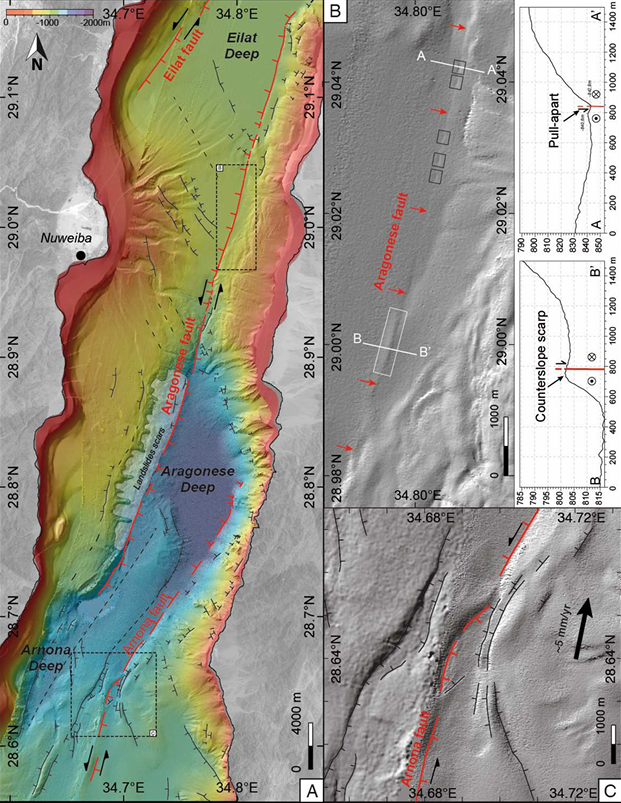 Figure 4
- Detailed fault map of the sinistral strike-slip fault system in the central GA. Direct evidence of surface rupture associated to the main subevent (see Fig. 2) of the 1995 Mw = 7.3 Nuweiba earthquake are found in box B.
- Sharp fault morphology suggesting very recent fault activation. Small changes of geometry along the Aragonese fault are responsible for small pull-apart (black squares) and counterslope scarp (white square).
- Detail of the fault zone between Aragonese Deep and Arnona Deep resulting from a complexity in the geometry of the Arnona fault. The red line represents the main active strike slip fault.
 Figure 5
- Southern part of the Gulf of Aqaba (see location on Figure 2). Dakar and Tiran Deeps are located between the sinistral strike-slip Arnona fault (red line) and the normal Dakar fault (bold black lines). The location of the main strike-slip fault is partly masked by diapiric foldings (black arrows) and secondary faulting (thin black and dashed black lines) associated with the destabilization of large salt deposits moving down from the Dahab plateau.
- Cross-sections across the Dahab plateau showing the eastward sloping and the topographic drop from the Dahab plateau toward the Dakar and Tiran deeps.
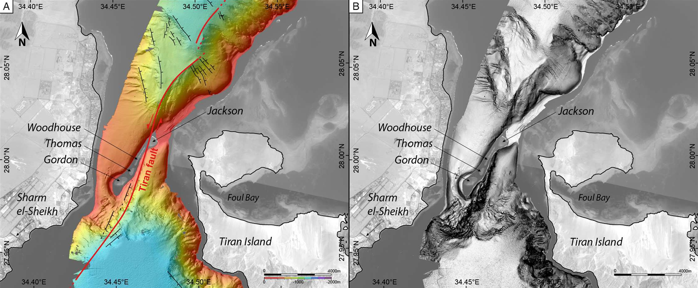 Figure 6
Strait of Tiran (see location on Figure 2).
- The sinistral strike-slip Tiran Fault is located between the Woodhouse and Jackson reefs. The sharp bathymetry to the North and to the South of the reef emphasizes the location of the fault. Red lines represent the main strike slip faults, black lines represent the main normal faults.
- Slope map of the Strait of Tiran, from low slope angle (white: 0°) to high slope angle (black: >45°).
- Gulf of Aqaba in Google Earth
 Gulf of Aqaba in Google Earth
click on image to explore this site on a new tab in Google Earth
 Fig. 1
(a) Regional tectonic map of the Dead Sea Transform and location of the Gulf of Aqaba/Elat
(b) Topographic image map of the southern Arava Valley showing location of the study area of the Elat Sabkha. Previously mapped faults in black lines (after Garfunkel, 1970; Garfunkel et al., 1981; Sneh et al., 1998). Previous study sites including Avrona Sabkha and Yovata Sabkha and locations of the paleoseismic trenches (in block circles)
- QT = Qatar trench (Klinger et al., 2015)
- AT = Avrona Trenches (Amit et al., 1999; Zilberman et al., 2005)
- ST = Shehoret trenches (e.g. Amit et al., 2002)
- GAE = Gulf of Aqaba/Elat
CMP shots discussed in this study from seismic lines SI-4047 and GI-2108 are plotted as light-blue dots and yellow dots, respectively. The blue rectangle marks the extent of the study area maps presented in Figs. 3 and 9. The pink line represents the location of the offshore high-resolution seismic profile by Hartman et al. (2014) detailed in Fig. 2b.
Kanari et al (2020)
 Figure 5
3D grain size distribution up to 2 mm (left) and radiocarbon dating results (right) along the canyon core MG10P27. Color bar represent % of grain size differential distribution by volume. Black dots represent the chronological age of the pelagic sediments, whereas diamonds represent the different color groups of LBF shells from within the MTDs.
Ash-Mor et al (2017)
 Figure 4
Grain size distribution (downcore spectrum of % volume per grain diameter) and 14C age determinations (cal BC/AD) of core P27 from the northern Gulf of Aqaba Elat. 14C age calibrated using Calib 7.0 (Stuiver and Reimer, 1993) and Marine13 calibration curve (Reimer et al, 2013).
Kanari et al (2015)
 Figure 5
Grain size distribution (downcore spectrum of % volume per grain diameter) of cores P17 (540 mbsl), P22 (316 mbsl) and P29 (282 mbsl) from the Northern Gulf of Aqaba-Elat; see Fig. 2 for core locations
Kanari et al (2015)
- Gulf of Aqaba in Google Earth
Gulf of Aqaba in Google Earth
click on image to explore this site on a new tab in Google Earth
- from Bektaş et al. (2024)

Sediment coring locations in the Gulf of Aqaba.
a) Tectonic setting in the eastern Mediterranean and the northern Red Sea.
b) The bathymetry of the Gulf of Aqaba and active faults (Ribot et al., 2021; Le B´eon et al., 2012) with black dots showing the coring locations. The main strike-slip faults are in red
- TF: Tiran Fault
- ArF: Arnona Fault
- AF: Aragonese Fault
- EF: Eilat Fault
- WAF: Wadi Araba
- x (Klinger et al., 2015)
- y (Amit et al., 1999; Zilberman et al., 2005)
- z (Amit et al., 2002)
- t (Kanari et al., 2020)
c-g) Close-up views of the coring locations in the Eilat, Aragonese, Dakar, Tiran and Hume deeps.
Bektaş et al. (2024)
- from Bektaş et al. (2024)
 Table 1
List of location coordinates (UTM Zone 36) and lengths of collected sediment cores.
Bektaş et al. (2024)
- from Bektaş et al. (2024)
 Fig. 2
U-channel radiographic images of prominent and well-preserved turbidites (Type I; red bars) in the sediments of the Gulf of Aqaba. Note the bioturbation and biogenic content (e.g., carbonaceous shells seen as whitish spots) in the background sedimentation. Event labeling is given in the lower left of each image.
Bektaş et al. (2024)
- from Bektaş et al. (2024)
Fig. 2U-channel radiographic images of prominent and well-preserved turbidites (Type I; red bars) in the sediments of the Gulf of Aqaba. Note the bioturbation and biogenic content (e.g., carbonaceous shells seen as whitish spots) in the background sedimentation. Event labeling is given in the lower left of each image.
Bektaş et al. (2024)
- from Bektaş et al. (2024)
 Fig. 3
U-channel radiographic images of different types of sedimentary events.
- Type I: Turbidites (red bars)
- Type II: Turbidite or Flooding (gray bars)
- Type III: Thick Flooding Sequence (yellow bars)
- from Bektaş et al. (2024)
Fig. 3U-channel radiographic images of different types of sedimentary events.
- Type I: Turbidites (red bars)
- Type II: Turbidite or Flooding (gray bars)
- Type III: Thick Flooding Sequence (yellow bars)
- from Bektaş et al. (2024)
 Fig. 4
Sedimentary events detected in the radiographic images of the Gulf of Aqaba cores, labelled by letters and indicated by red, gray, and yellow vertical bars. Depths of 210Pb and 14C measurements are also shown by green and blue rectangles next to the images, respectively. In the table, raw and calibrated 14C results are listed. The raw and composite depths, and the depths corresponding on core 11 (after stratigraphical correlation) for each 14C sample are also given. In the lower right, results of 210Pbex measurements on cores 3, 7, and 17 and the corresponding sedimentation rates (SR) are presented.
Bektaş et al. (2024)
- from Bektaş et al. (2024)
Fig. 4Sedimentary events detected in the radiographic images of the Gulf of Aqaba cores, labelled by letters and indicated by red, gray, and yellow vertical bars. Depths of 210Pb and 14C measurements are also shown by green and blue rectangles next to the images, respectively. In the table, raw and calibrated 14C results are listed. The raw and composite depths, and the depths corresponding on core 11 (after stratigraphical correlation) for each 14C sample are also given. In the lower right, results of 210Pbex measurements on cores 3, 7, and 17 and the corresponding sedimentation rates (SR) are presented.
Bektaş et al. (2024)
- from Bektaş et al. (2024)
 Fig. 5
Magnetic susceptibility (MS), sand content, and Zr/Sr profiles produced along selected cores (at least one core per basin) through the Gulf of Aqaba. Sedimentary events shown in Fig. 4 are also shown as horizontal bars in this figure. Event labeling and color code for different types of events are the same as in Fig. 4. See the Supplementary Material (E-SUPP 1) for detailed descriptions of sedimentary events for all of the cores.
Bektaş et al. (2024)
- from Bektaş et al. (2024)
Fig. 5Magnetic susceptibility (MS), sand content, and Zr/Sr profiles produced along selected cores (at least one core per basin) through the Gulf of Aqaba. Sedimentary events shown in Fig. 4 are also shown as horizontal bars in this figure. Event labeling and color code for different types of events are the same as in Fig. 4. See the Supplementary Material (E-SUPP 1) for detailed descriptions of sedimentary events for all of the cores.
Bektaş et al. (2024)
- from Bektaş et al. (2024)
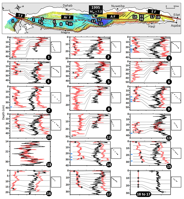 Fig. 6
Chemostratigraphical correlation of composite Sr/Ca ratio profiles (event-free) of each core (red curves) to core 11 (black curves). Depths of sedimentary events and radiocarbon dates are shown as dots and blue rectangles, respectively. Bi-plots next to each graph show the original composite depths (y-axes) versus the modified depths on core 11 (x-axes) of the tie-lines (gray lines). Details of the chemostratigraphical correlation procedure are presented in the Supplementary Material (E-SUPP 2).
Bektaş et al. (2024)
- from Bektaş et al. (2024)
Fig. 6Chemostratigraphical correlation of composite Sr/Ca ratio profiles (event-free) of each core (red curves) to core 11 (black curves). Depths of sedimentary events and radiocarbon dates are shown as dots and blue rectangles, respectively. Bi-plots next to each graph show the original composite depths (y-axes) versus the modified depths on core 11 (x-axes) of the tie-lines (gray lines). Details of the chemostratigraphical correlation procedure are presented in the Supplementary Material (E-SUPP 2).
Bektaş et al. (2024)
- from Bektaş et al. (2024)
 Fig. 7
Calibrated radiocarbon dates, and the age-depth model determined by OxCal P_Sequence function. Two reworked samples (9–33.04 and 7–38.70) were not included in the P_Sequence code, which can be found in the Supplementary Material (E-SUPP 3). The list and depths of all sedimentary events are also shown.
Bektaş et al. (2024)
- from Bektaş et al. (2024)
Fig. 7Calibrated radiocarbon dates, and the age-depth model determined by OxCal P_Sequence function. Two reworked samples (9–33.04 and 7–38.70) were not included in the P_Sequence code, which can be found in the Supplementary Material (E-SUPP 3). The list and depths of all sedimentary events are also shown.
Bektaş et al. (2024)
- from Bektaş et al. (2024)
 Fig. 8
Plot of Probability Distribution Functions (PDFs) of Type I and Type II events along the Gulf of Aqaba. Horizontal black lines mark the dates of historical earthquakes in the region. Major earthquakes that triggered extensive turbidites all along the gulf are seen as major anomalies on the summed PDFs profile. The scale of x-axis changes around CE 800. Time windows for the prehistorical surface rupturing events at the Qatar trenching site (x in Fig. 1, Klinger et al., 2015) are also shown. Note the recurrence intervals varying between 400 and 700 years and also the absence of extensive coeval turbidites in the southern half of the gulf since CE 1588.
Bektaş et al. (2024)
- from Bektaş et al. (2024)
Fig. 8Plot of Probability Distribution Functions (PDFs) of Type I and Type II events along the Gulf of Aqaba. Horizontal black lines mark the dates of historical earthquakes in the region. Major earthquakes that triggered extensive turbidites all along the gulf are seen as major anomalies on the summed PDFs profile. The scale of x-axis changes around CE 800. Time windows for the prehistorical surface rupturing events at the Qatar trenching site (x in Fig. 1, Klinger et al., 2015) are also shown. Note the recurrence intervals varying between 400 and 700 years and also the absence of extensive coeval turbidites in the southern half of the gulf since CE 1588.
Bektaş et al. (2024)